Chapter 4: Operation
Firmware – S2011 and S3012
Revision: 1 (9/98) 30 © Saftronics, Inc.
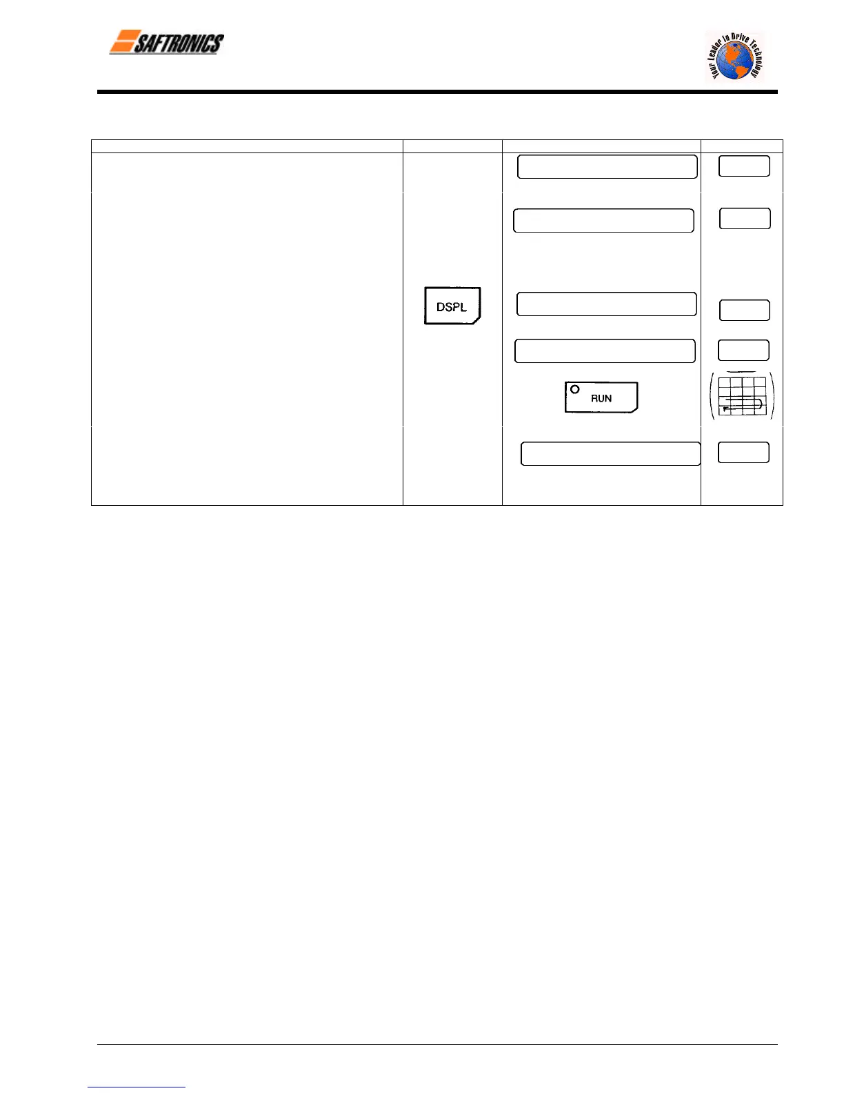
Table 11 Typical Operation by Control Circuit Terminal Signal
Description Key Sequence Digital Operator Display LED Display
¬
Power ON
• Display frequency reference value. 0.0
Fref
REMOTE mode is preset at the factory REMOTE LED (SEQ, REF) ON
-
Frequency Setting
• Input frequency reference voltage 60.0
Fref
(current) by control circuit Terminal FV For reference voltage 10V
or FI and verify the input value by the
Digital Operator.
Output Frequency Display
• Select output frequency monitor display.
0.0
Fout
®
Forward Run
• Close between control circuit Terminals 60.0
Fout
SI and SC to perform forward run. RUN LED ON
¯
Stop
• Open between control circuit Terminals
SI and SC to stop operation.
0.0
Fout
STOP LED ON
(RUN LED blinking
during deceleration)
efesotomasyon.com - Control Techniques,emerson,saftronics -ac drive-servo motor