EB 8384-3 EN 5-9
Installation
Î Make sure that the vent plug is locat-
ed at the bottom when the control
valve is installed to allow any con-
densed water that collects to drain
off.
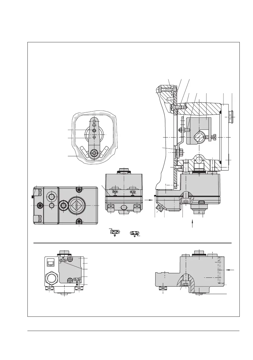
b) Type3277 Actuator
Î Required mounting parts and accesso-
ries: Table 5-6
Î Observethetraveltableonpage5-5.
Actuators with 175 to 750 cm² effective
areas (see Fig.5-6)
Mount the positioner on the yoke. The signal
pressure is routed to the actuator over the
connection block (12), for actuators with fail-
safe action "actuator stem extends" internal-
ly through a hole in the valve yoke and for
"actuator stem retracts" through an external
pipe.
1. Place follower clamp (3) on the actuator
stem, align it and screw tight so that the
mounting screw is located in the groove
of the actuator stem.
2. Mount cover plate (10) with narrow side
of the cut-out (Fig.5-6, on the left) point-
ing towards the signal pressure connec-
tion. Make sure that the gasket (14)
points towards the actuator yoke.
3. Foractuatorswith355,700or750cm²,
remove the follower pin (2) on the M le-
ver (1) on the back of the positioner from
pin position 35, reposition it in the hole
for pin position 50 and screw tight.
Whiledoingso,holdtheleverinthe
middle to ensure that it does not rest at
the end stops.
ExtendsRetracts
2
12
1
SUPPLY
13
B
C
1.1
1.2
12
12.1
12
12.2
12.11216
16 16
12.2
SUPPLY
SUPPLYG
G 3/8
A
M lever
Cut-out of
cover plate (10)
Actuator stem extends
Actuator stem retracts
Connection
block (old) with
switch plate (13)
Actuator stem
1 Lever
1.1 Nut
1.2 Disk spring
2 Follower pin
3 Follower clamp
10 Cover plate
11 Cover
11.1 Ventplug
12 Connection block
12.1 Screw
12.2 Stopper or connection for external
piping
13 Switch plate
14 Gasket
15 Molded seal
16 Gasket
Marking
ViewA
ViewC
ViewB
Fig.5-6: Direct attachment – Signal pressure connection for Type3277 Actuator with 175 to 750cm²

 Loading...


