OfficeServ 7200-S INSTALLATION
TECHNICAL MANUAL PART 3 MAY 2010
3.17
Ports & LEDs Function Description
CLK LED This LED indicates whether this board is a master or slave.
-
On: The board has received the synchronization clock from the counterpart
station.
- Off: Using synchronous clock for internal clock.
TP1 LED This LED indicates whether the T1 is established.
- This LED turns on once the T1 is established.
TP2 LED This LED indicates whether the PRI is connected.
- This LED turns on once the PRI is connected.
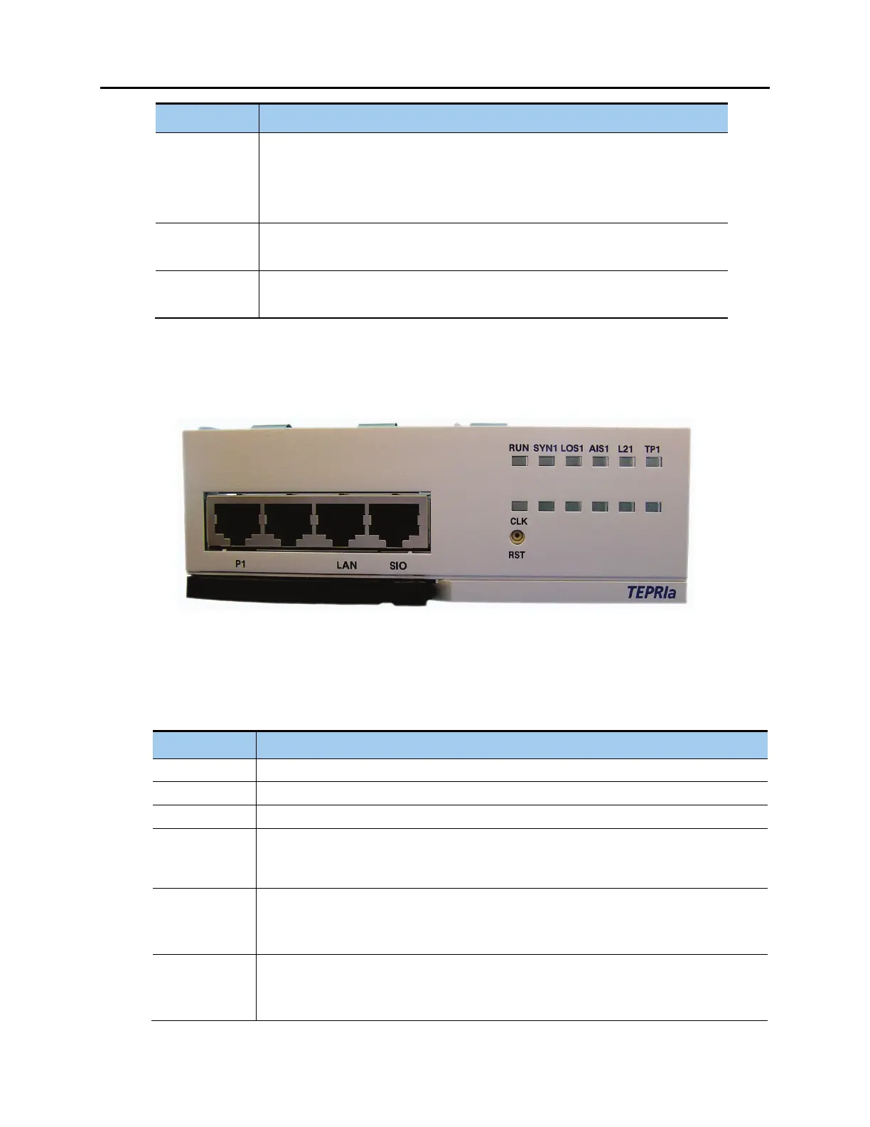
FRONT VIEW OF TEPRIa BOARD
The front view of the TEPRIa board is shown in the picture below.
Figure 3.19 Front View of the TEPRIa
Front panel components of the TEPRIa:
Table 3.7 Ports and LEDs of the TEPRIa
Port, LED Function Description
P1 Port for connecting T1/E1/PRI cables
LAN Port for connecting to Ethernet (reserved for future use)
SIO Serial port for internal Samsung engineering use only.
TP1 LED Indicates the type of the circuit connected to port P1
- On: PRI in operation
- Off: T1/E1 in operation
L21 LED
This LED indicates the operation status of Layer 2
- On: The PRI Layer 2 is operating properly. PRI message is being received.
- Off: The PRI Layer 2 is operating abnormally.
AIS1 LED
This LED indicates whether the T1/E1 remote alarm has been generated.
- On: The remote alarm has been generated. All one’s are being received (Error)
- Off: The remote alarm has not been generated (Normal).












 To Next Page