2 INSTALLATION PLANNING
The ST3400 has been designed to ensure maximum interoperability with all types
avionics. Contact Sandel with any questions about interfacing to specific avionics
equipment not covered in the installation drawings in this manual.
2.1 General Information
To simplify installation, after signals are wired to the ST3400 pins, on-screen
setups are used in a post-installation procedure. Maintenance menu pages provide
a function selection capability. For most FMS systems, selections are made by
equipment make and model.
Refer to the installation schematics in an Appendix of this manual for details on
connecting required components.
2.2 Allowed Sensor Configuration Matrix – Class A
2.2.1 Required Sensors (Class-A)
1. Heading
2. GPS position
3. Localizer and Glideslope
4. Radar Altitude
5. Baro Rate (Vertical Speed)
6. Flaps
7. Gear (only if the aircraft has retractable gear).
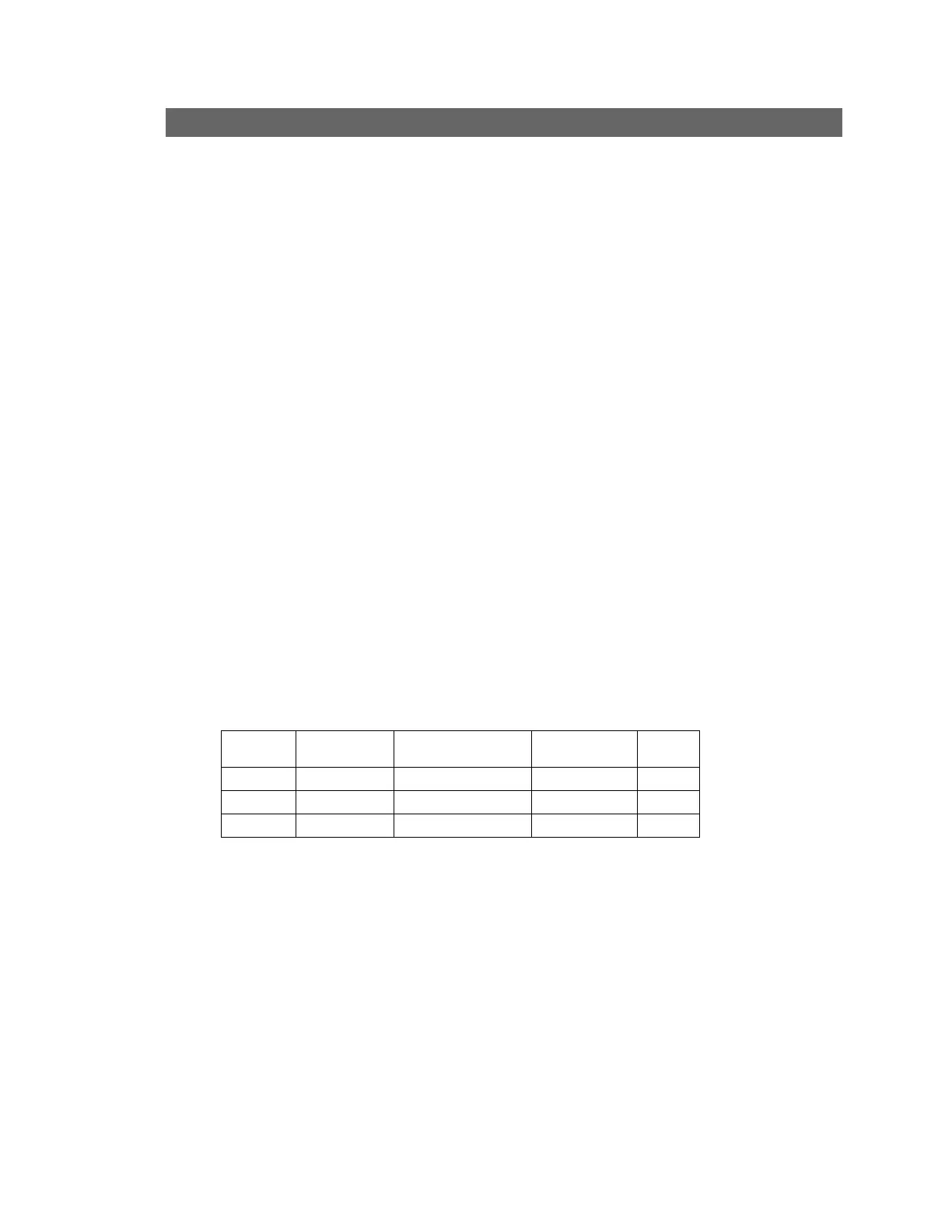
2.2.2 Additional Required Sensors, allowed configurations (Class-A)
Config
GPS Alt Corr. Baro Alt Press. Alt OAT
(Item shown blank not required)
Contact factory for configurations other than those listed.
2.3 Allowed Sensor Configuration Matrix – Class B
2.3.1 Required Sensors (Class-B)
1. Heading
2. GPS position
82002-IM-L ST3400 INSTALLATION MANUAL
2-1