4.7 P3 Connector
For electrical characteristics, see the table in section 4.9 by referencing the signal
type indicated in italics. Signal types enclosed in parentheses indicate
functionality that is reserved.
Pin # Name Signal Type (dependent on maintenance page selection)
1
Aircraft Pwr
9
Aircraft Pwr
2
n/c
10
n/c
3
Aircraft Ground
11
Aircraft Ground
4
GS OVRD Lamp
12
5
n/c
In Factory use only DO NOT CONNECT
13
TAWS INH
In Optional external TAWS INH switch
Discrete Valid
6
Lamp Test
In Optional external enunciator test
Discrete Valid
14
Warning Lamp
7
Caution Lamp
15
TAWS INH Lamp
8*
Selectable
Discrete*
(Out) TCAS INH (TAWS Warn or Caution);
-or- GPWS FAIL ;
-or- TCAS INDICATOR discrete to TCAS-II
-or- AUDIO ENABLE relay drive
(Open Drain) Selectable on SYSTEM maintenance page
* Note: All discrete outputs sink 50ua of current when off. If used as TCAS
INH to a TCAS processor, this connection may require an external 30k-50k
pullup resistor in order for the discrete input of the TCAS to be at the proper
‘high’ (unasserted) voltage. If necessary, check with a voltmeter during
installation.
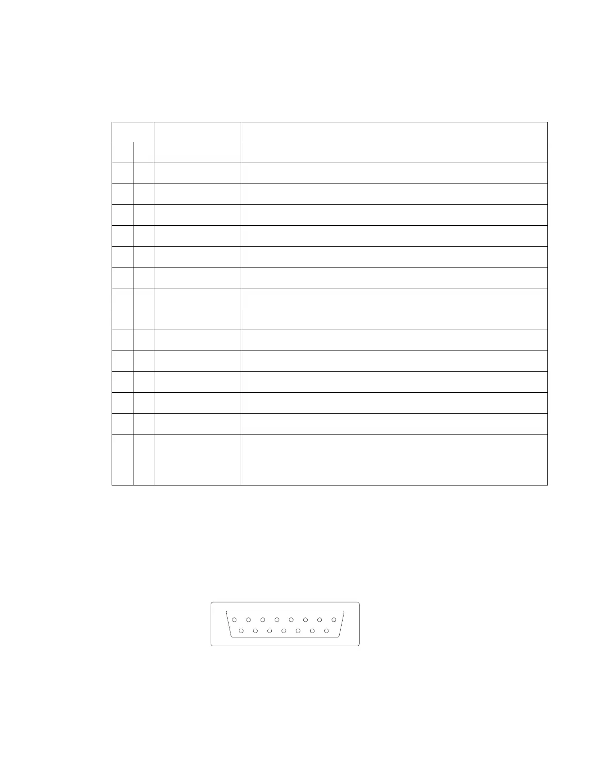
4.7.1 View of Mating Connector to P3
Outside View
(Mating Connector)
82002-IM-L ST3400 INSTALLATION MANUAL
4-9