P1 Connector (continued from previous page)
Pin # Name Signal Type (dependent on maintenance page selection)
41
Flaps-X /
Spare1A
A429/419 A side 429/419
(R422) + side 422
(R232) Ground side
(A407) Synchro X
27
Flaps-Y /
Spare1B
A429/419 B side 429/419
(R422) - side 422
(R232) Rx
(A407) Synchro Y
12
N/C
42
429 Out A
Out
A429 A Side - Alert output to FDR - High Speed (100Kbps)
28
429 Out B
Out
A429 B Side - Alert output to FDR - High Speed (100Kbps)
13
RS232TxD
43
n/c
In Factory use only DO NOT CONNECT
Discrete
29
OAT Probe
In Connect other lead to pin-1 GROUND.
A575 Excitation
14
n/c
44
n/c
30
Audio LL Out
Out
Audio LL Low Level Audio output, requires external amplifier
15
Speaker Audio
Out
Out Clone of audio from Audio1 which has the capability of
driving 8 ohm speaker directly. Volume separately
trimmed with respect to LL audio, which acts as master.
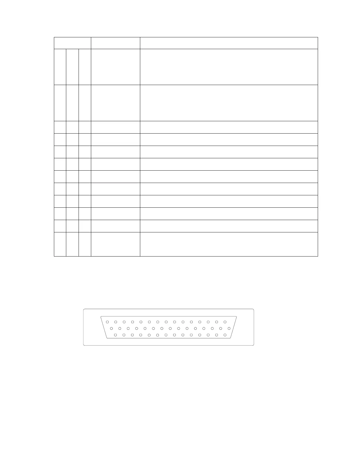
4.5.1 View of Mating Connector to P1
15
30
44
14
29
43
13
28
42
12
27
41
11
26
40
10
25
39
9
24
38
8
23
37
7
22
36
1
16
6
21
35
5
20
34
4
19
33
3
18
32
2
17
31
Outside View
(Mating Connector)
82002-IM-L ST3400 INSTALLATION MANUAL
4-5