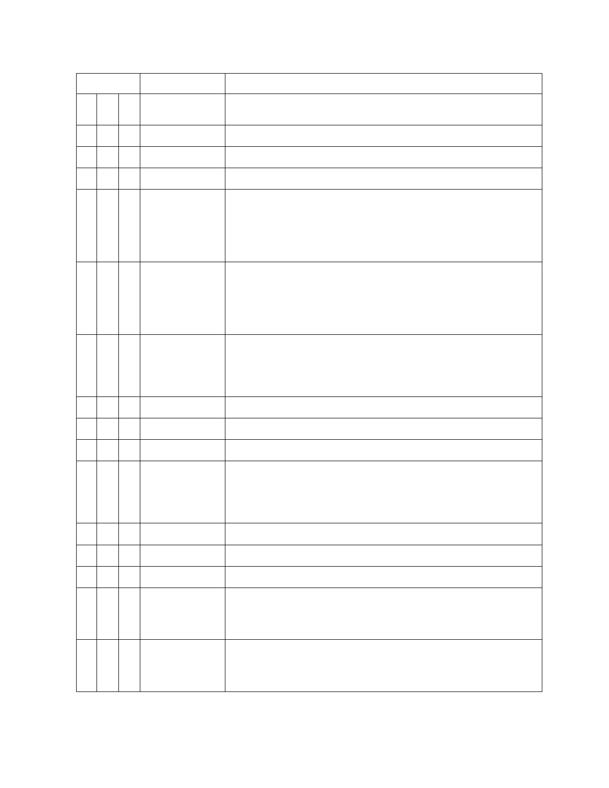
P1 Connector (continued from previous page)
Pin # Name Signal Type (dependent on maintenance page selection)
6
GS1 LL Flag In+
In Differential pair to pin 36
GS Flag Note: For use with external SUPERFLAG see installation
drawing for series resistor required.
36
GS1 LL Flag In-
In Differential pair to pin 6.
GS Flag
22
In Differential pair to pin 7.
GS Polarity: + indicates above glideslope, fly-down indication.
7
In Differential pair to pin 22.
GS Polarity: + indicates below glideslope, fly-up indication
37
Airdata1A
A429/419 A side 429/419
(R422) + side 422
(R232) Ground side
A407 AC resolver Fine Sine Altitude
Synchro X Fine Altitude
23
Airdata1B
A429/419 B side 429/419
(R422) - side 422
(R232) Rx
A407 AC resolver Fine Cosine Altitude
Synchro Y Fine Altitude
8
Alt1 / VS1 Gnd
In Note: Differential signals paired with pin 39.
A429/419 A side 429/419
(R422) + side 422
(R232) Ground side
(A407) Synchro X
Alt DC Coarse Ground at source
38
VS1 Signal
In
VS Sig DC voltage - 5V to + 5V = -10,000 to +10000 FPM
24
VS1 Ref-
In
VS Ref Note: -12Vdc excitation reference
9
VS1 Ref+
In
VS Ref Note: +12Vdc excitation reference
39
Alt1 DC Coarse
In Note: Differential signals paired with pin 8.
A429/419 B side 429/419
(R422) - side 422
(R232) Rx
(A407) Synchro Y
25
TAS1 Sig
10
TAS1 Ref
40
Airdata1 Valid
In
Discrete Valid ADC Analog, Note: Not used when 429 is data source.
26
FMS1 A
Secondary
(A429) A side 429
(R422) + side 422
(R232) Ground side
11
FMS1 B
Secondary
(A429) B side 429
(R422) - side 422
(R232) Rx
4-4 ST3400 INSTALLATION MANUAL 82002-IM-L