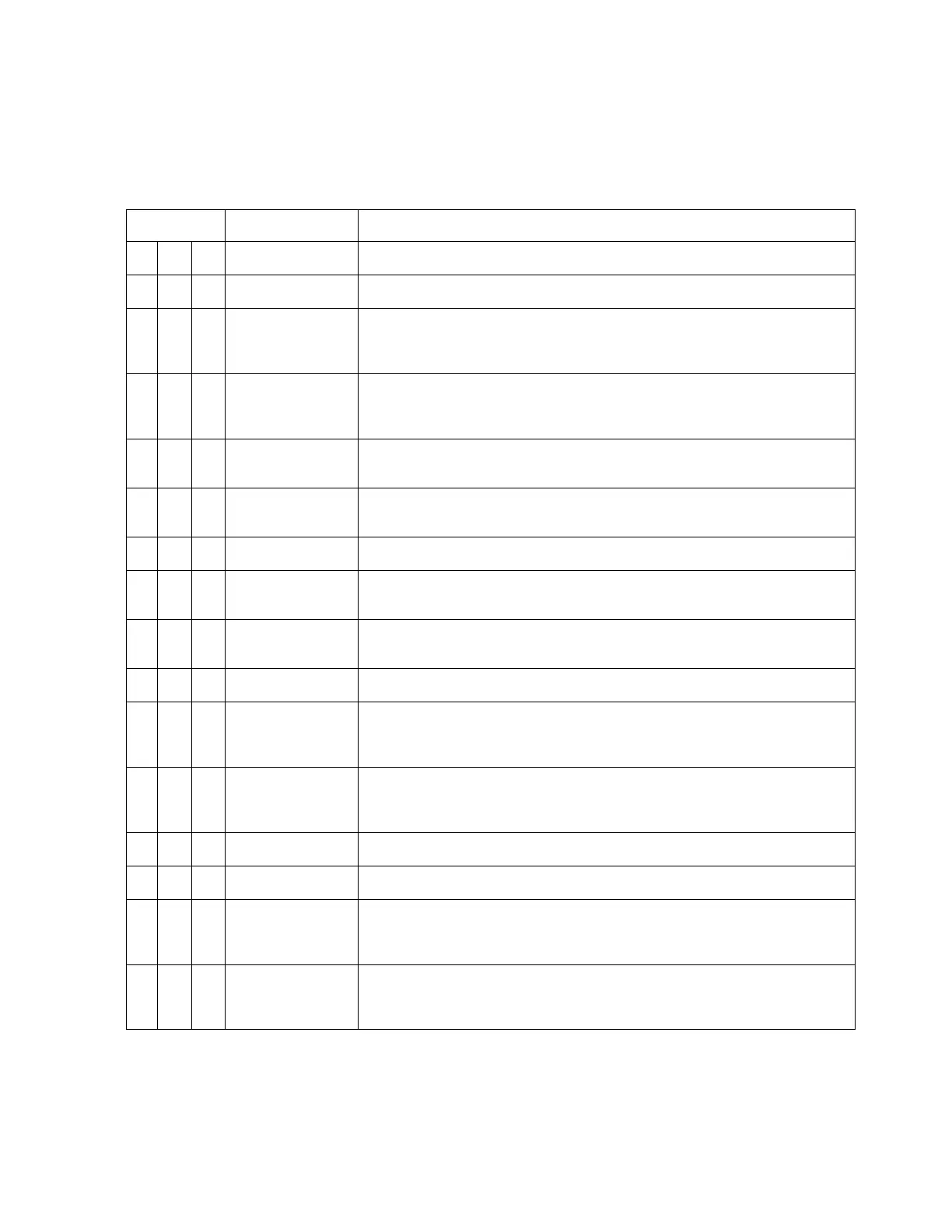
4.6 Connector P2
For electrical characteristics, see the table in section 4.9 by referencing the signal
type indicated in italics. Signal types enclosed in parentheses indicate
functionality that is reserved.
Pin # Name Signal Type (dependent on maintenance page selection)
16
Inverter Exc.
In Note: May be same or different than P2-16 inverter source.
Inverter 26Vac Excitation for items on connector P1
1
Shield Gnd
31
FMS2A Primary
A429 A side 429
(RS422) + side 422
17
FMS2B Primary
A429 B side 429
(RS422) - side 422
2
TCAS A
A429 A side 429
32
TCAS B
A429 B side 429
18
In
Discrete Valid Discrete Open/Gnd or Open/+28VDC
3
Hdg2A
A429 A side 429
A407 Synchro X [Z grounded]
33
Hdg2B
A429 B side 429
A407 Synchro Y [Z grounded]
19
Hdg2 Valid
In
Discrete Valid Hdg Analog, Note: Not used when 429 is data source.
4
ADF2A
A429 A side 429
DC Sin DC Sine
A407 Synchro X [Z grounded]
34
ADF2B
A429 B side 429
DC Cos DC Cosine
A407 Synchro Y [Z grounded]
20
ADF2 DC Ref
In
ADF Ref ADF DC, Note: Not used when 429 or XYZ is data source.
5
ADF2 Valid
In
Discrete Valid ADF Discrete, Note: Not used when 429 is data source
35
Nav2A
In Note: For composite inputs see P2-42
A429 A side 429
(RS422) + side 422
21
Nav2B
In Note: For composite inputs see P2-42
A429 B side 429
(RS422) - side 422
4-6 ST3400 INSTALLATION MANUAL 82002-IM-L