P2 Connector (continued from previous page)
Pin # Name Signal Type (dependent on maintenance page selection)
41
Spare
(A429) A side 429
(R422) + side 422
(R232) Ground side
(A407) Synchro X
27
Spare
(A429) B side 429
(R422) - side 422
(R232) Rx
(A407) Synchro Y
12
Spare2C
42
Nav1 Composite
In VOR Bearing and Localizer Deviation input.
A710, A711 Used when ARINC 429 data is not used
28
Nav2 Composite
In VOR Bearing and Localizer Deviation input.
A710, A711 Used when ARINC 429 data is not used
13
RA1 FAIL
In
Discrete Valid If RA1 configured: <14VDC indicates RA 1 Fail
43
Audio Increase
Discrete Valid Activates audio level increase.
29
AP Engage
14
Gear Down
44
Flaps Ldg
In
Discrete Valid Indicate flaps are in landing (not takeoff) configuration
30
429A Interlink
Out For dual installations to feed cross-side system
A429 A side 429
15
429B Interlink
Out For dual installations to feed cross-side system
A429 B side 429
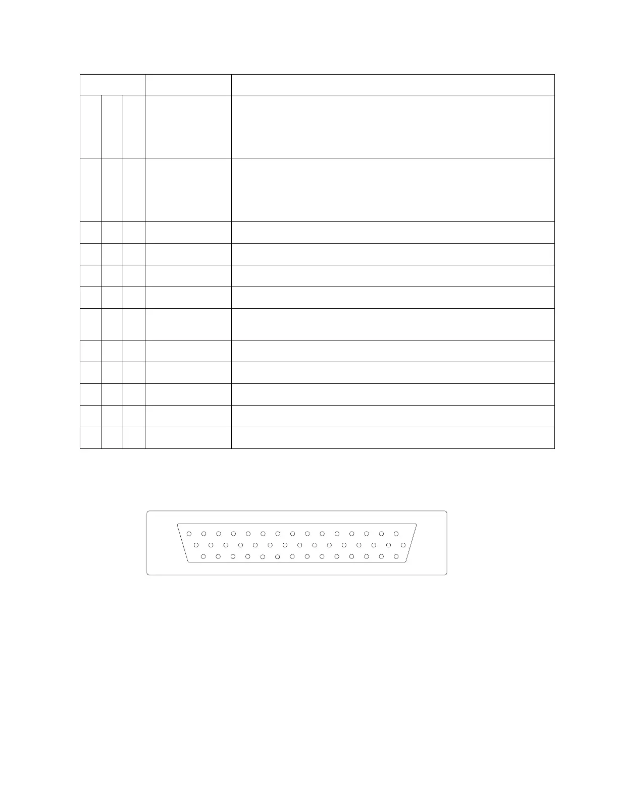
4.6.1 View of Mating Connector to P2
15
30
44
14
29
43
13
28
42
12
27
41
11
26
40
10
25
39
9
24
38
8
23
37
7
22
36
1
16
6
21
35
5
20
34
4
19
33
3
18
32
2
17
31
Outside View
(Mating Connector)
4-8 ST3400 INSTALLATION MANUAL 82002-IM-L