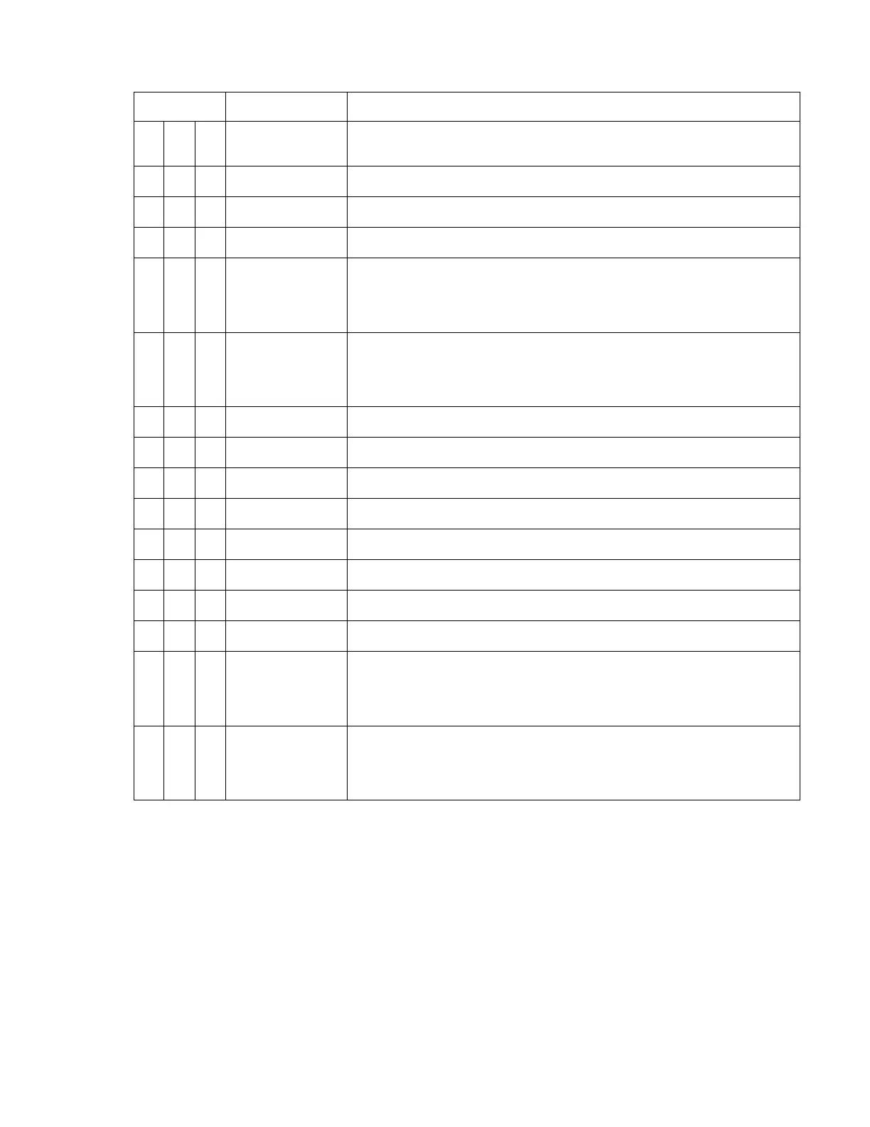
P2 Connector (continued from previous page)
Pin # Name Signal Type (dependent on maintenance page selection)
6
GS2 LL Flag In+
In Differential pair to pin 36
GS Flag Note: For use with external SUPERFLAG see installation
drawing for series resistor required.
36
GS2 LL Flag In-
In Differential pair to pin 6.
GS Flag
22
In Differential pair to pin 7.
GS Polarity: + indicates above glideslope, fly-down indication.
7
In Differential pair to pin 22.
GS Polarity: + indicates below glideslope, fly-up indication
37
Digital Airdata
2A
A429 /419 A side 429/419
(R422) + side 422
(R232) Ground side
23
Digital Airdata
2B
A429 /419 B side 429/419
(R422 ) - side 422
(R232) Rx
8
Spare Analog 1
38
Spare Analog 2
24
Flaps Ovrd
9
GS Ovrd
39
Pressure Altitude
1 Analog
In Pressure Altitude 0.25 VDC/1Kft or 0.3175 VDC/1K ft
25
Spare Analog 3
10
VS1 Rate (CIC)
In 10 VDC +/-5 VDC, 0.5 VDC/1K ft
40
In
Discrete Valid Discrete Open/Gnd or Open/+28VDC.
26
FMS2 A
Secondary
(A429) A side 429
(R422) + side 422
(R232) Ground side
11
FMS2 B
Secondary
(A429) B side 429
(R422) - side 422
(R232) Rx
82002-IM-L ST3400 INSTALLATION MANUAL
4-7