#1 VOR/ILS
Receiver, generate
external Glideslope
signal, vary the input
deviation. Test at 0, +-
GS1 GS 1 value for “GS DEV DDM”
deviation should match generated
signal.
#2 VOR/ILS
Receiver, generate
external VOR signal
at 0 degrees TO.
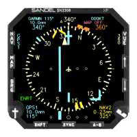
NAV2 Nav 2 value VOR BEARING should
read 0 degrees TO, calibrate BRG on
page 6 if required. Verify value “ILS
NOT TUNED” is shown.
#2 VOR/ILS
Receiver, generate
external Localizer
signal, vary the input
deviation. Test at 0, +-
NAV2 Nav 2 value should indicate “ILS
TUNED” and “LOC DEV DDM”
deviation should match generated
signal.
#2 VOR/ILS
Receiver, generate
external Glideslope
signal, vary the input
deviation. Test at 0, +-
GS2 GS 2 value for “GS DEV DDM”
deviation should match generated
signal.
Rotate HSI till Course
Pointer is greater than
+-90 degrees from
Back Course Back Course will be enabled when
Course Pointer is greater than +-90
degrees from Lubber Line
7.2.17 RADAR ALTIMETER
Note: The Radar Altimeter test maybe performed by pressing the Radar
Altimeter self test button, or by utilizing a Radar Altimeter test set. This
manual references the use of the Radar Altimeter self test button and does
not provide the information to setup and test the Radar Altimeter with a
test set. For those applications utilizing relying on the use of a Radar
Altimeter Test set, the operator should consult Radar Altimeters
manufactures test setup and procedures for operation of the test set. The
test that will be performed to validate the ST3400 TAWS/RMI operation
with the Radar Altimeter will be tests defined below.
7-26 ST3400 INSTALLATION MANUAL 82002-IM-L