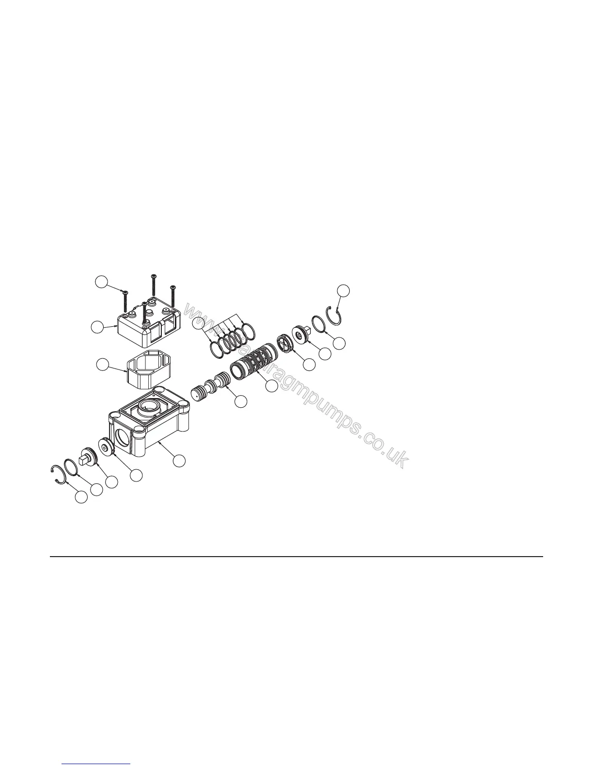
MAIN AIR VALVE ASSEMBLY PARTS LIST
ITEM PART NUMBER DESCRIPTION QTY
1 031-140-000 Main Air Valve Assembly 1
1-A 031-139-000 Spool Assembly 1
1-B 095-094-551 Body, Air Valve 1
1-C 132-029-552 Bumper 2
1-D 165-096-551 Cap, Muffl er 1
1-E 165-115-552 Cap, End 2
1-F 530-028-550 Muffl er 1
1-G 560-020-360 O-Ring 8
1-H 675-044-115 Ring, Retaining 2
1-J 710-015-115 Screw, Self-tapping 4
For pumps equipped with PTFE Coated Hardware
1 031-140-002 Air Valve Assembly 1
(Includes all items used on 031-140-000 except:)
1-J 710-015-308 Screw Self tapping 4
1-H 675-044-308 Ring, Retaining 2
For pumps equipped with PTFE coated hardware option:
1 031-141-000 Air Valve Assembly 1
(Includes all items used on 031-140-000 minus
items 1-D, 1-F & 1-J)
For pumps with alternate Mesh or Sound Dampening muffl ers
or piped exhaust:
1 031-041-002 Air Valve Assembly 1
(Includes all items used on 031-141-000 except:)
1-H 675-044-308 Ring, Retaining 2