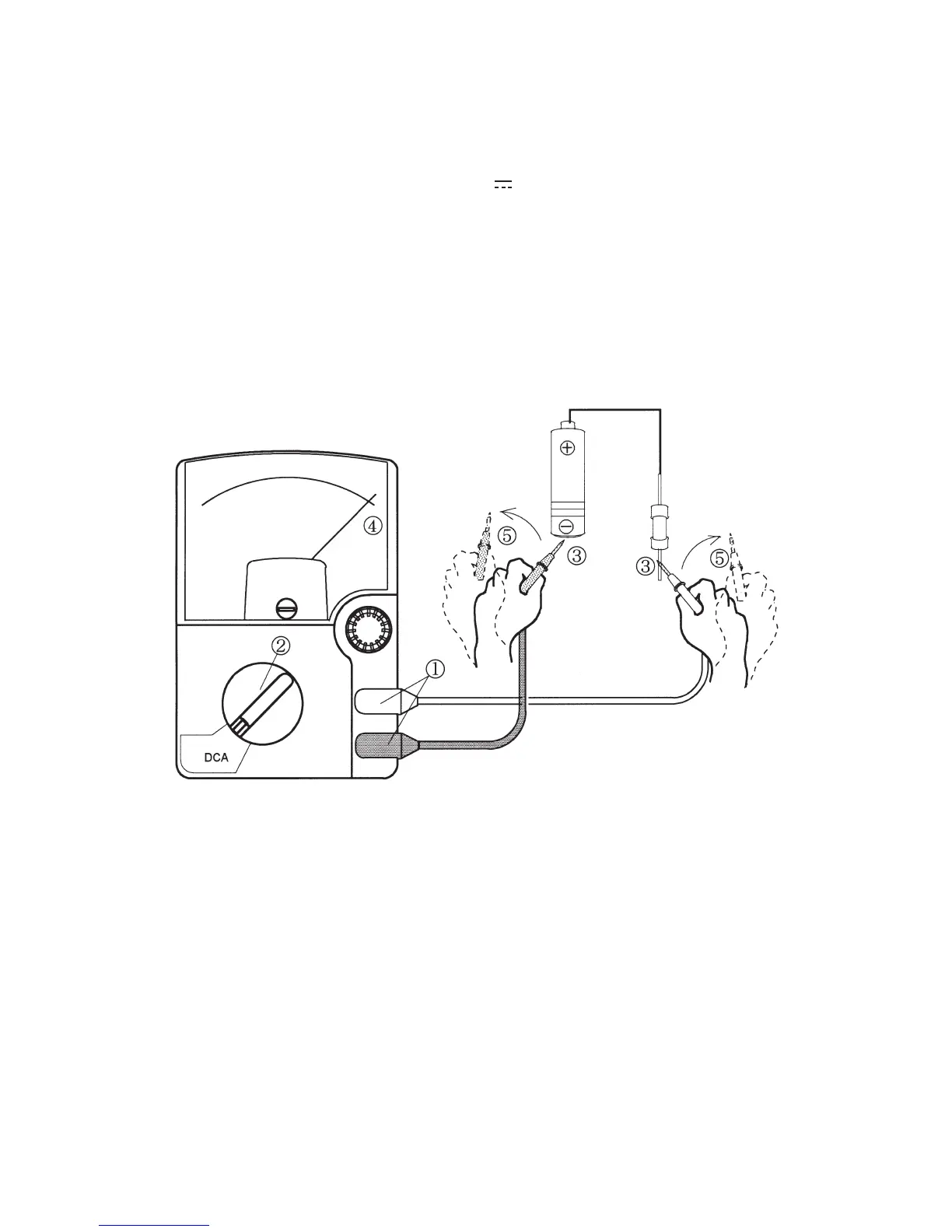
EasyManua.ls Logo

Sanwa SP21 - Page 25

Sanwa SP21
52 pages
Print Icon
To Next Page IconTo Next Page
To Previous Page IconTo Previous Page
Loading...

DRAWING No SP21 18-1805 2040 2040

󰴤

󰴥
󰴦

󰴧
󰴨


 3Measurement procedure
Connect the black plug of the test lead to the input
terminal and the red plug to the +input terminal.
 ②Set the range selector knob to an appropriate DCA range.
 ③Apply the black test pin to the negative potential side of the
circuit to measure and the red test pin to the positive potential
side.
 ④Read the move of the pointer by VA scale.
 ⑤After measurement, remove the red and black test pins from
the circuit measured.





Table of Contents

Related product manuals