-23-
[Before adjustment]
- Make sure each Red, Green and Blue LCD panel unit has been correctly installed.
- Input a grid pattern signal.
- Adjustment requires a 2.0mm hex wrench. Remove cabinet top following to the “Mechanical Disassemblies”.
1. Insert paper etc. in Red or Blue panel to block the red
or blue light so that either green and red or green and
blue lights are projected. (For example, when adjust
Red panel convergence, project green and red lights,
and when adjust Blue panel, project green and blue
lights.)
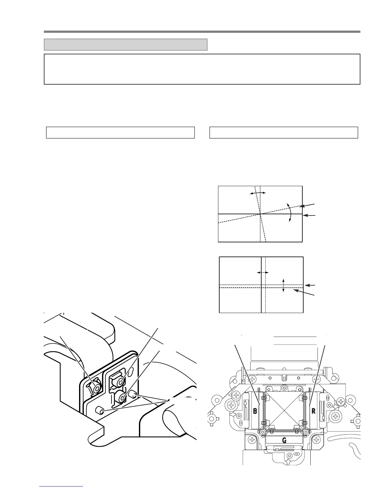
2. Loosen 2 screws “D” (Fig.1) using the 2.0mm hex
wrench.
3. Turning the screw “A”, align so that the Red (or Blue)
horizontal lines are parallel to the Green horizontal
lines (Fig.1-a).
4. Turning screw “B”, align the Red (or Blue) vertical
lines onto the Green vertical lines (Fig.1-b).
5. Turning screw “C”, align the Red (or Blue) horizontal
lines onto the Green horizontal lines (Fig.1-b).
6. By repeating steps 3 to 5, align the Red (or Blue) grid
lines onto the green lines.
7.Tighten the 2 screws “D” to fix the Red (or Blue) panel
unit.
RED/BLUE PANEL CONVERGENCE
1. Adjustment screw “A” turns the image (Fig.1-a).
2. Adjustment screw “B” moves the image right and left
(Fig.1-b).
3. Adjustment screw ”C” moves the image up and down
(Fig.1-b).
[Image Movement and Screw Turning]
C: up/down
B: right/left
A: angle
D: Fixing
Fig.1-a
Red or Blue
Green
A
Fig.1-b
Red or Blue
Green
C
B
Red LCD panel
Blue LCD panel
For convergence adjustment, use Green as the reference standard. Align Red and Blue with Green by adjusting
the position and angle of the Red and Blue LCD panels. Screws “A”, “B”, “C” (Fig.1) are for convergence adjust-
ment.
CONVERGENCE ADJUSTMENT
Fig.1
Fig.2
■ Optical Adjustments