-27-
After replacing the Power Board, PF.C. Board, readjust
the Output voltage adjustment as follows.
1. Connect a digital voltmeter to pins 1 (+) and 3 (-) of
K6C.
2. Adjust the voltage by using VR01 as following.
AC Input Reading
230V 370V ±2V
120V 320V ±2V
Caution:
Be sure to connect the lamp when taking this adjust-
ment.
OUTPUT VOLTAGE ADJUSTMENT
● Circuit Adjustments
CAUTION: The each circuit has been made by the fine adjustment at factory. Do not attempt to adjust the follow-
ing adjustments except requiring the readjustments in servicing otherwise it may cause loss of perfor-
mance and product safety.
[Adjustment Condition]
● Input signal
Video signal ..................1.0Vp-p/75Ω terminated, 16 steps gray scale or color bar pattern
Computer signal............0.7Vp-p/75Ω terminated, 16 steps gray scale pattern
MCI signal * ..................16 steps gray scale pattern from PC Card
● Picture control mode ---------- “NORMAL” mode unless otherwise noted.
Note:
* Please refer to “Service Adjustment Menu Operation” for entering to the service mode and adjusting the service
data.
* It is not available the MCI mode for model which does not provide the PC Card slot.
Electrical Adjustments
Presetting
1. Receive the 16-step grey scale video signal.
2. Set to VIDEO mode.
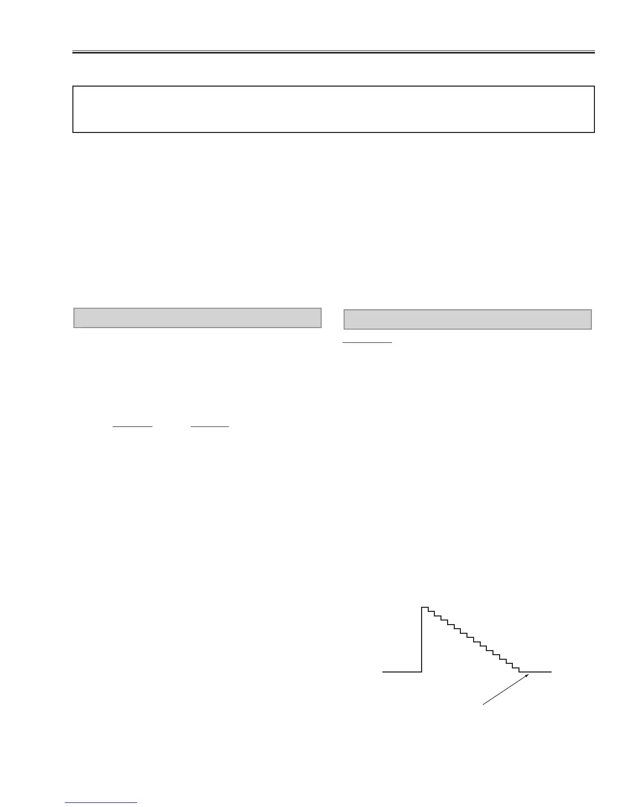
[R-PEDESTAL ADJUSTMENT]
3. Connect an oscilloscope to test point “TP221R” (+)
and chassis ground (-).
4. Enter to the service mode, select item no. “27” and
change data value to adjust the pedestal level and
black level to be same level.
[G-PEDESTAL ADJUSTMENT]
5. Connect an oscilloscope to test point “TP221G” (+)
and chassis ground (-).
6. Select item no. “28” and change data value to adjust
the pedestal level and black level to be same level.
[B-PEDESTAL ADJUSTMENT]
7. Connect an oscilloscope to test point “TP221B” (+)
and chassis ground (-).
8. Select item no. “29” and change data value to adjust
the pedestal level and black level to be same level.