To each boards
50
27
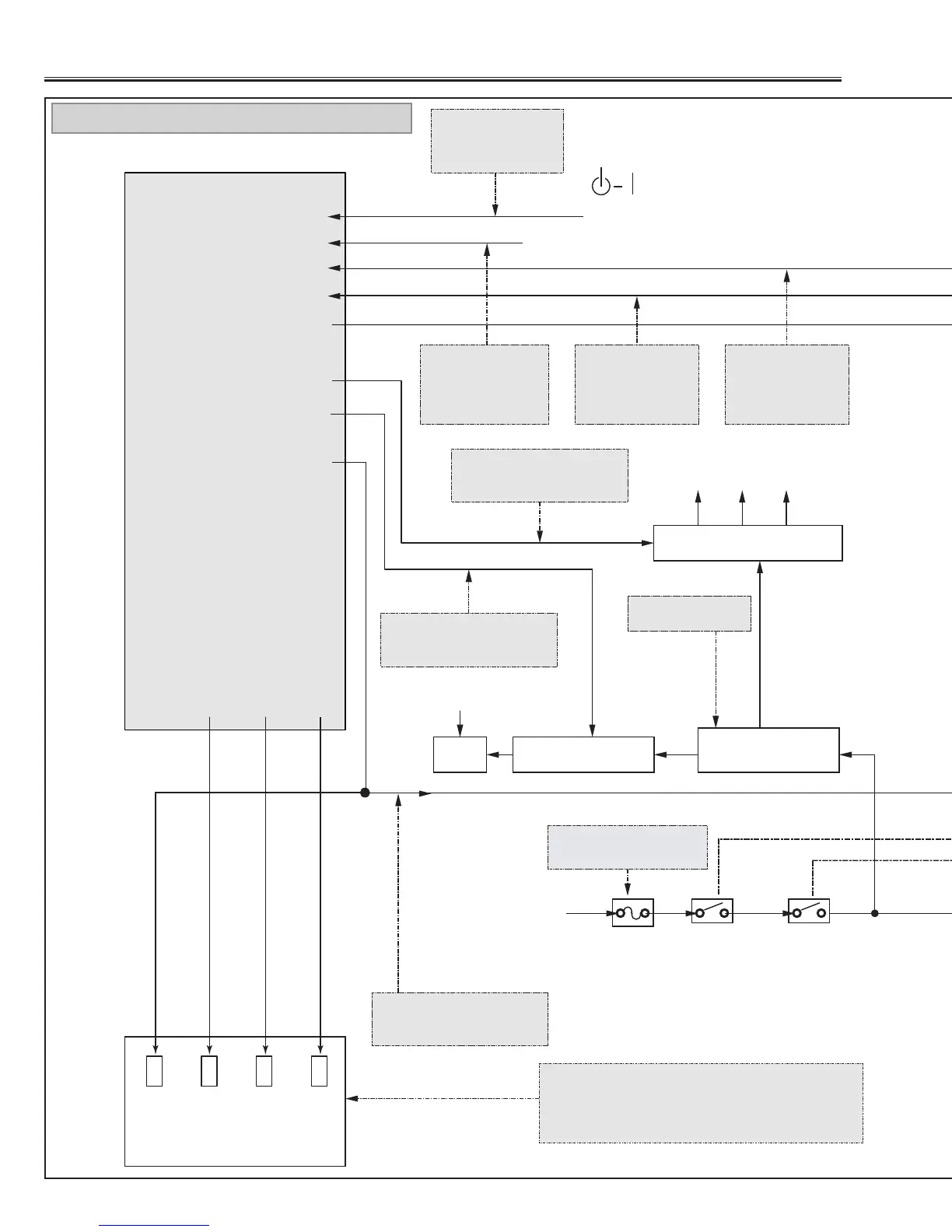
IC1901 SUB CPU
INDICATORS
ON/OFF BUTTON
47
26
AC INPUT
FAN
KEY2
POWER FAIL
LAMP DET.
29
LAMP SW.
54
LAMP BST_SW.
34
5V_SW.
44
FAN DRIVE
31
READY
30
WARNING
32
LAMP REPLACE
TEMP DET.
12V 15V 5V
F901
FUSE
SW902
THERMAL SW.
Is fuse (F901) blown?
SW904
INTER LOCK
SW.
POWER FAIL
LAMP
READY
TEMP
WARNING
LAMP
REPLACE
Check that the LAMP indicator and READY indicator
are lighting.
If both of indicators are not lighting, check the primary
side of the power supply circuit or S5V of standby power
supply circuit.
Switching power
supply
Check signal at pin 5
of T651
IC66A, Q671, Q681
IC67A, IC68A, IC69A
When power on/off
button is pressed, the
input voltage at pin 47
comes High.
Check that the
POWER FAIL signal
at pin 50 is correct.
L : abnormal
Check that the FAN DRIVE
signal at pin 44 is correct.
H : Power ON
Check that the 5V_SW signal
at pin 34 is correct.
H : Power ON
Check that the
LAMP DET. signal at
pin 27 is correct.
H : abnormal
Check that the
TEMP DET. signal at
pin 26 is correct.
L : abnormal
Check that the LAMP_SW
signal at pin 29 is correct.
H : Power On
H: ON
L: ABNORMAL
L: ABNORMAL
H:ON
H:ON
H:ON
H: ABNORMAL