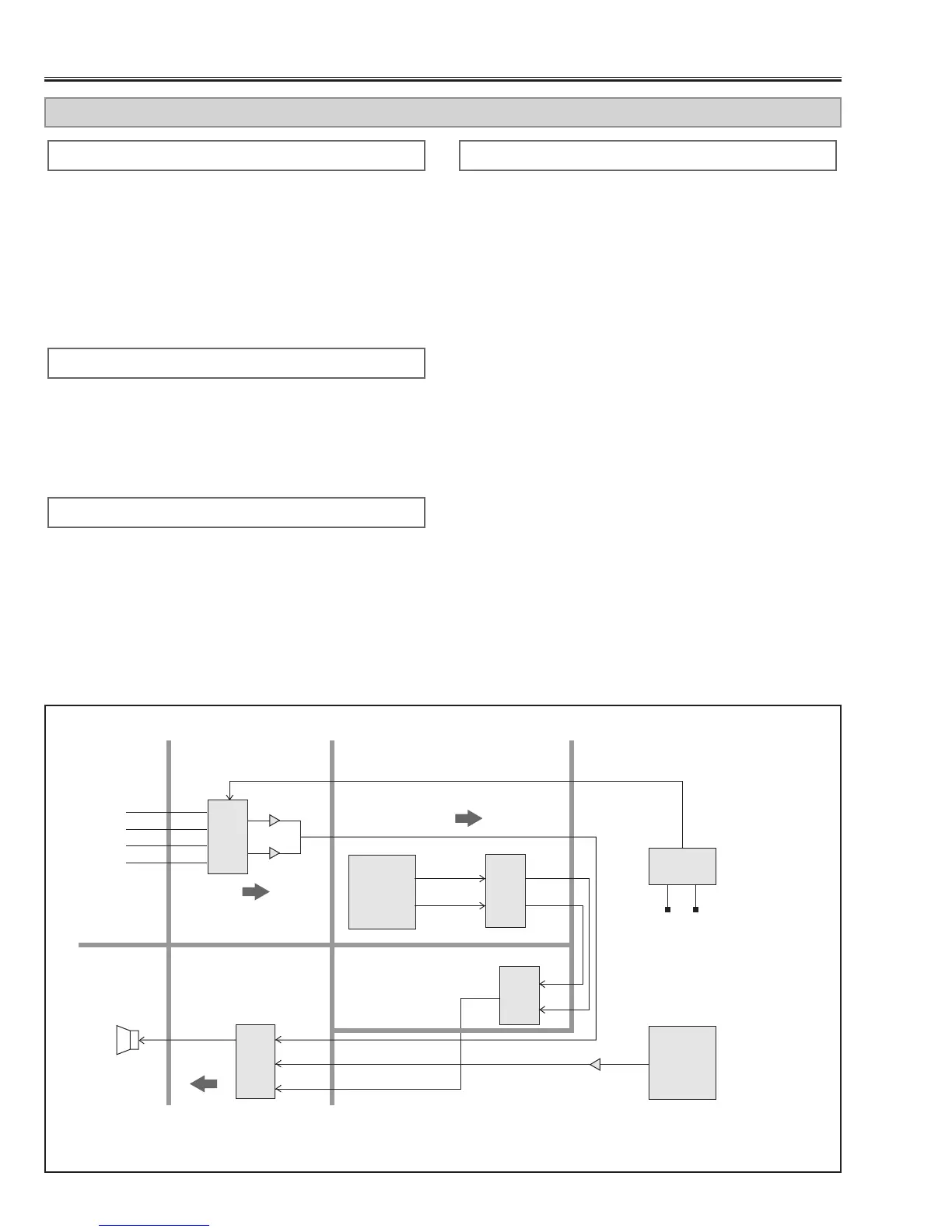
SCAN CONV.
1. Check that sound volume control signal is correct.
Pin 4 of IC001
2. Check that audio signal is observed at pin 2 of
IC001.
3. Check the MUTE signal at pin 3 of IC001.
Pin 3 of IC001 ......................................MUTE On: H
4. Check that Vcc-voltage(+12V) is applied at pins 1
and 9 of IC001.
POWER BOARD
1. Check that the Vcc-voltage(+9V) is applied at pins 3-
6 of K3802.
2. Check that the AV/CG switching signal is correct.
Pin 9, 10 of IC5001 ........................................ AV : L
CG : H
3. Check that audio signal is observed at following
points.
Pins 9-10 of K3802, pins 11-14 of K3801
1. Check that the AV/CG switching signal is correct.
Pin 4 of IC1904 .............................................. AV : L
CG : H
2. Check that the MUTE signal is correct.
Pin 39 of IC1901 ..................................MUTE On: H
1. Check that sound volume control signal is correct.
Pin 4 of IC431
MAIN COMP-C BOARD
MAIN COMP-B BOARD
AV, AV SUB BOARD
NO SOUND