-29-
Electrical Adjustments
Presetting
1. Receive the 16-step grey scale video signal.
2. Set to VIDEO mode.
[R-VIDEO GAIN ADJUSTMENT]
3. Connect an oscilloscope to test point “TP2211R” (+)
and chassis ground (-).
4. Enter to the service mode, select item no. “49” and
change data value to adjust “a” to be 1.12 ±0.02Vp-p.
[G-VIDEO GAIN ADJUSTMENT]
5. Connect an oscilloscope to test point “TP2221G” (+)
and chassis ground (-).
6. Enter to the service mode, select item no. “50” and
change data value to adjust “a” to be 1.12 ±0.02Vp-p.
[B-VIDEO GAIN ADJUSTMENT]
7. Connect an oscilloscope to test point “TP2231B” (+)
and chassis ground (-).
8. Enter to the service mode, select item no. “51” and
change data value to adjust “a” to be 1.12 ±0.02Vp-p.
Pedestal level = Black level
(a)
VIDEO-GAIN ADJUSTMENT-[AV]
Presetting
1. Receive the 16-step grey scale computer signal.
2. Set to COMPUTER mode.
[R-VIDEO CENTER ADJUSTMENT]
3. Connect a digital voltmeter to test point “TP511” (+)
and chassis ground (-).
4. Adjust voltage to be 7.30 ±0.05V by using VR501.
[G-VIDEO CENTER ADJUSTMENT]
5. Connect a digital voltmeter to test point “TP512” (+)
and chassis ground (-).
6. Adjust voltage to be 7.30 ±0.05V by using VR531.
[B-VIDEO CENTER ADJUSTMENT]
7. Connect a digital voltmeter to test point “TP513” (+)
and chassis ground (-).
8. Adjust voltage to be 7.30 ±0.05V by using VR561.
VIDEO CENTER ADJUSTMENT
1. Receive the 16-step grey scale computer signal.
2. Set to COMPUTER mode.
3. Connect an oscilloscope to test point “TP3571” (+)
and chassis ground (-).
4. Adjust “a” to be 5.0 ±0.1V by using VR3571.
(a)
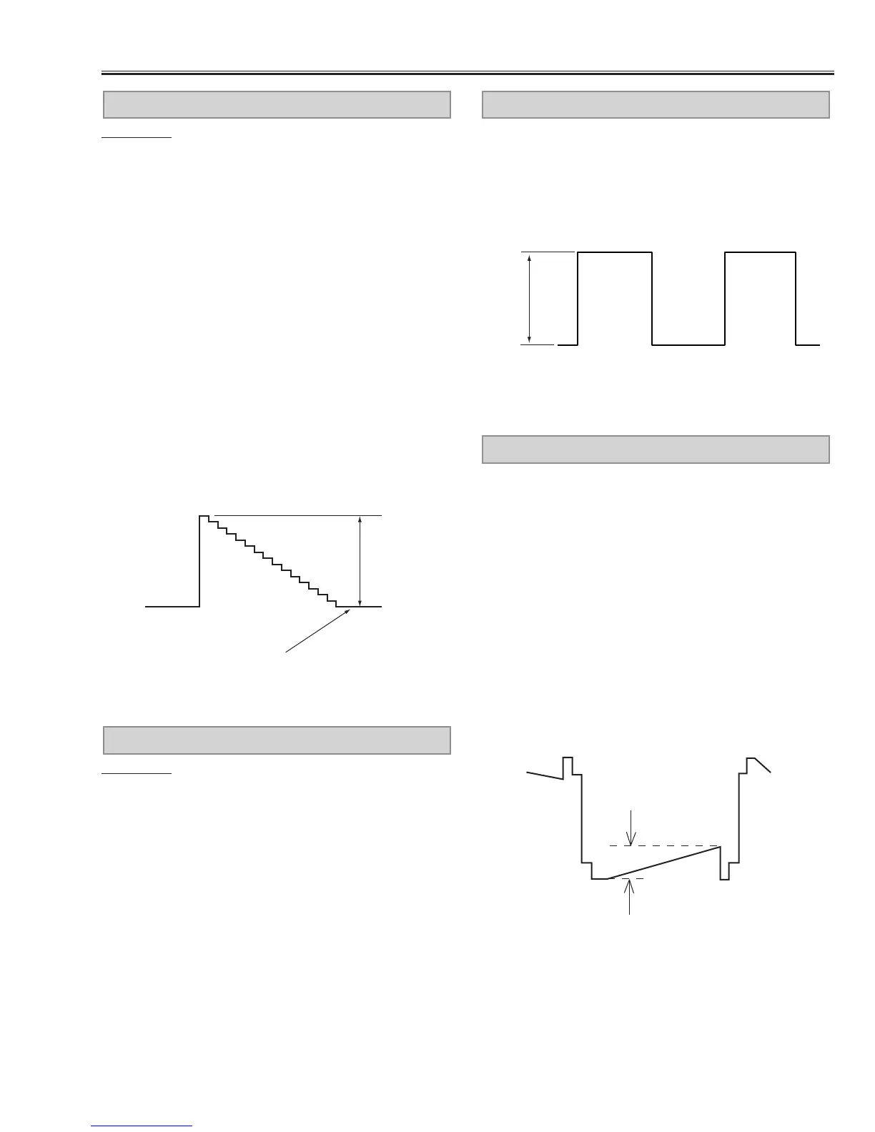
NRS ADJUSTMENT
[GAMMA OFF ADJUSTMENT-CG]
1. Receive the 16-step gray scale computer signal.
2. Set to COMPUTER mode.
3. Connect an oscilloscope to test point “TP512” (+) and
chassis ground (-).
4. Enter to the service mode, select item no. “0” and
change data value to adjust “a” to be 1.70 ±0.01Vp-p.
[GAMMA OFF ADJUSTMENT-AV]
5. Receive the 16-step gray scale video signal.
6. Set to VIDEO mode.
7. Connect an oscilloscope to test point “TP512” (+) and
chassis ground (-).
8. Enter to the service mode, select item no. “0” and
change data value to adjust “a” to be 1.70 ±0.01Vp-p.
GAMMA OFF VIDEO ADJUSTMENT
(a)
 Loading...