EasyManua.ls Logo

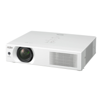
Sanyo PLC-XU355A User Manual

Sanyo PLC-XU355A
126 pages
To Next Page IconTo Next Page
Page #1 background imageLoading...
Page #1 background image
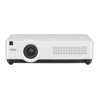
Multimedia Projector
SERVICE MANUAL
PRODUCT CODE
PLC-XU355A PLC-XU305A
1 122 473 20 (KG5AE) 1 122 463 20 (KB5AE)
1 122 474 20 (LG5AE) 1 122 464 20 (LB5AE)
1 122 474 22 (LG5CE) 1 122 464 22 (LB5CE)
Original Version
REFERENCE NO. SM5111166-00
FILE NO.
Model No. PLC-XU355A
PLC-XU305A
U.S.A, Canada,
Europe, U.K, Asia
Chassis No. KG5-XU355A00
KB5-XU305A00
Match the Chassis No. on the unit's cabinet bottom with the
Chassis No. in the Service Manual.
If the Original Version Service Manual Chassis No. does
not match the unit’s, additional Service Literature is re-
quired. You must refer to “Notices” to the Original Service
Manual prior to servicing the unit.
Table of Contents

Other manuals for Sanyo PLC-XU355A

Questions and Answers:

Sanyo PLC-XU355A Specifications

General IconGeneral
ResolutionXGA (1024 x 768)
Contrast Ratio2000:1
Lamp Life2000 hours (Normal Mode), 3000 hours (Eco Mode)
Zoom Ratio1.2x
Projection System3LCD
Screen Size30 - 300 inches
Display TypeLCD
Lamp TypeUHP
InputsS-Video, Composite Video
OutputsVGA
Noise Level29 dB (eco)
Power Consumption280 W (normal)

Summary

Safety Instructions

Safety Precautions

Precautions for safe projector servicing.

Service Personnel Warning

Warnings for service personnel regarding lamp heat and UV radiation.

Circuit Protections

Thermal Switch

Detects abnormal temperature and stops operation; resets automatically.

Maintenance

Lamp Replacement

Lamp Replacement Procedure

Step-by-step instructions for replacing the projector lamp safely.

Mechanical Disassembly

Optical Parts Disassembly

Adjustments

Adjustments After Parts Replacement

Table indicating necessary adjustments after replacing specific parts.

Optical Adjustments

Contrast Adjustment

Procedure to adjust the contrast by manipulating polarized glass mounting base.

Integrator Lens Adjustment

Steps to adjust the integrator lens assembly for white color uniformity.

Relay Lens-Out Adjustment

Procedure to adjust the relay lens assembly for white color uniformity.

Electrical Adjustments

Service Adjustment Menu Operation

Guide on entering, navigating, and exiting the projector's service mode.

Circuit Adjustments

General cautions and conditions for performing circuit adjustments.

Auto Calibration and Adjustments [PC/Component]

Procedures for auto-calibration and adjustments for PC/Component input.

Auto Calibration and Gain Adjustments [Video]

Procedures for auto-calibration and gain adjustments for video input.

Test Points and Locations

Main Board Test Points

Diagram illustrating test point locations on the main circuit board.

Service Adjustment Data Table

Chassis Block Diagrams

Chassis Overview Diagram

High-level block diagram of the projector's chassis components.

System Control Block Diagram

Block diagram illustrating the projector's system control circuitry.

Lamp Control Block Diagram

Block diagram detailing the lamp control and ballast circuit.

Power Supply & Protection Circuit Diagram

Block diagram of power supply and protection circuits.

Fan Control Circuit Diagram

Block diagram of the fan control and temperature sensing circuits.

Troubleshooting

Indicator and Projector Condition Correlation

Table correlating indicator lights with projector status.

No Power Troubleshooting

Steps to diagnose and resolve power-related issues.

No Picture Troubleshooting

Diagnostic steps for issues related to the projector displaying no image.

No Sound Troubleshooting

Steps to diagnose and resolve audio output problems.

Electrical Parts List

Electrical Parts Location

Mechanical Parts List

Optical Parts Location

Diagram showing the location of optical assemblies.

Mechanical Parts List Details

List of mechanical parts with their respective numbers and descriptions.

Diagrams and Drawings

Schematic Diagrams & Printed Wiring Board Drawings

Identifies the availability of schematic diagrams and printed wiring boards.

Component Pin Descriptions

Related product manuals