106
Pin Assignment Chart
Female Interface Connector:
14-contact round connector, with
screw-lock hardware for cable gland
Pin Assignment Chart
14-contact:
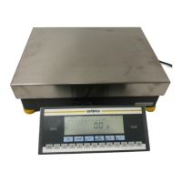
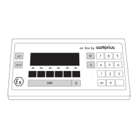
Scale/YAC01FC-X display and
control unit
12-contact:
Zener Barrier
IDI01-Z, YDI02-Z, YDI03-Z
14-contact 12-contact RS-232 signal RS-485 signal
1
)
Round Round (SBI and xBPI) (xBPI)
connector connector
GA
3
) Control output “heavier” Control output “heavier”
K B Data output (TxD) RxD – TxD – N
J C Data input (RxD) RxD – TxD – P
N D Data Terminal Ready (DTR) —
M E Signal GND Signal GND
FG
3
) Control output “lighter” Control output “lighter”
A H Clear to Send (CTS) —
EJ
3
) Control output “equal” Control output “equal”
O – Universal switch
2
) Universal switch
2
)
DL
3
) Control output “set” Control output “set”
Connect low-ohmic shield to the connector case
1
) RS-485 interface available on request
2
) See “Universal Remote Switch” in the section “Device Parameters” for more information
on the switch functions
3
) Control output available only for YDI03-Z
! Important Note:
Only electrical equipment with a maximum voltage rating V
m
of 250 V is permitted to be
connected to the Zener barrier. The voltage rating V
Z
of this Zener barrier is 12 V.