32
RC-F-24.TIF
RC-F-52.TIF
RC-F-53.TIF
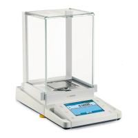
Exchanging the Analog PCB
– Open the balance (see page 23).
– Remove the connectors (B, C, D and E) from the digital PCB (204) and
unplug the cables from the mountings of the upper frame (208 / 211).
– Remove the fastening screws (F) and digital PCB (204) along with the
intermediate cover plate (205) and set them aside.
– Now remove the screw (G) from the rear panel of the balance and lift off
the upper enclosure frame (208).
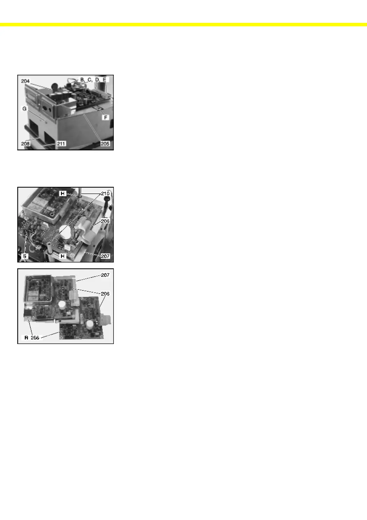
– Remove the system interface connector (S) from the analog PCB (206)
and unsolder cables of the temperature sensors.
Important Note: Please write down the way the cables of the temperature sensors are
soldered.
– Remove the retainer rings (H) from the PCB holders (210) and the
connecting cables from the openings in the analog PCB (206).
– Remove the analog PCB (206) along with the spacer plate (207) from
the PCB holders (210).
– Unscrew the analog PCB (206) from the spacer plate (207).
– Now transfer the precision resistor from the old analog PCB (206) (R 266)
to the new PCB (206).
– Attach the new PCB (206) onto the spacer plate (207).
– Place the analog PCB (206) along with the spacer plate (207) on the
PCB holders (210) and fasten it with the retainer rings (H).
– Route the connecting cables through the openings in the analog PCB
(206).
– Plug the system interface cable (S) into the socket of the analog PCB
(206) and solder the cables of the temperature sensors as marked.
– Reposition the upper enclosure frame (208) and refasten the screw (G).
– Place the digital PCB (204) along with the intermediate cover plate (205)
back onto the PCB holders (209), route the connecting cables through the
openings in the intermediate cover plate (205), and fasten the PCB (204)
and intermediate cover plate (205) with 2 screws (F) (10dNm) onto the
holders (210).
– Now insert the connecting cables into the retainers on the enclosure frame
parts (208 / 211) and the connectors (B, C, D and E) into the sockets on
the digital PCB (204).
– Close the balance housing (see page 24).
Important Note: The specific data of the new analog PCB must be transferred to the
EEPROM of the processor on the digital PCB. To do so, use the SARTOCAS
program for the PSION server. Please refer to the program description for
the proper procedure. Once this is done, you can finish your work.
Afterwards, the balance needs to be adjusted (Linearity,Span Adjustment).