24
RC-F-24.TIF
RC-F-25.TIF
RC-F-23.TIF
RC-F-26.TIF
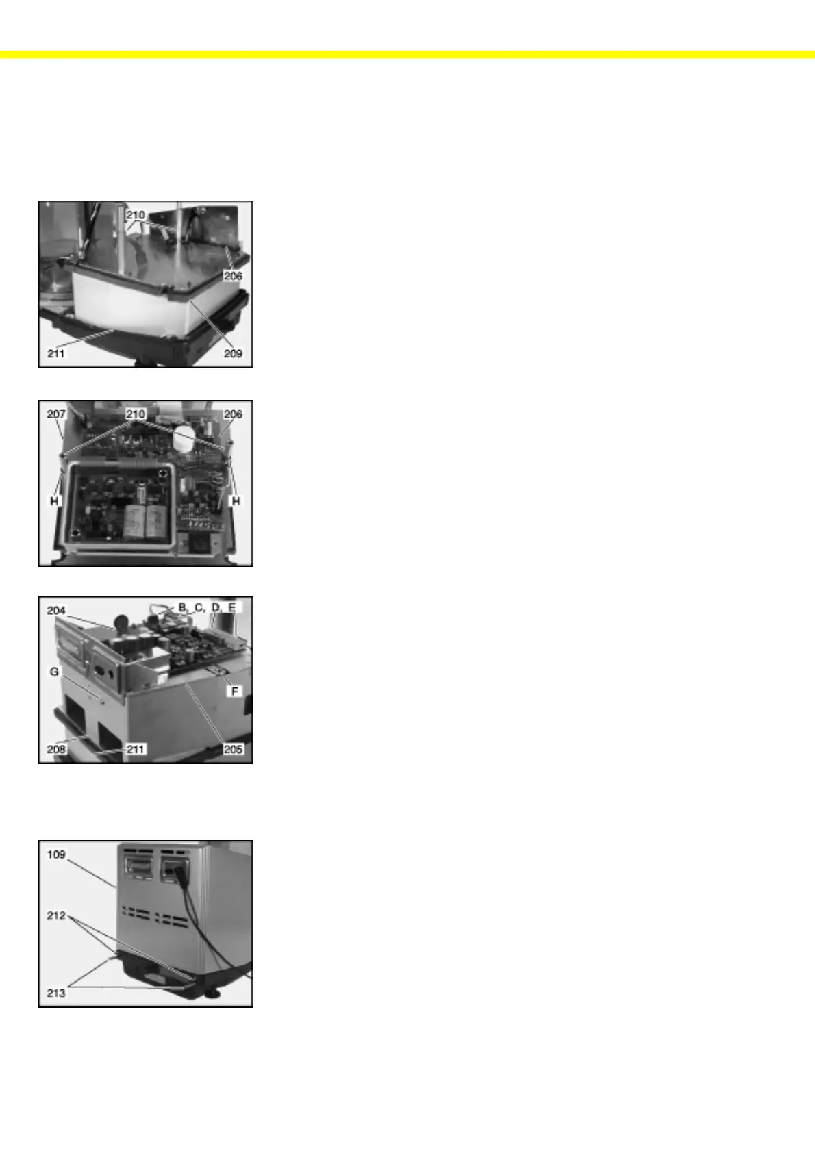
Installing PCBs and Enclosure
Warning! The following steps are necessary only if you have cleaned the weighing
system or exchanged the PCBs.
– Install the lower part of the enclosure frame (211) along with the analog
PCB (206), PCB holders (210) and weighing system on the base plate.
– Attach the insulation plate (209) and route the connecting cables through
the cable openings.
– Place the analog PCB (206) along with the spacer plate (207) on the
PCB holders (210) and fasten them using the retainer rings (H).
– Route the connecting cables through the cable openings in the analog
PCB (206).
– Now reposition the upper part of the enclosure frame (208) and fasten
screw (G).
– Place the digital PCB (204) along with the intermediate cover plate (205)
on the PCB holders (210), route the connecting cables through the open-
ings in the plate (205), and fasten the PCB (204) and the plate (205) to
the PCB holders (210) using 2 screws (F) (10dNm).
– Now insert the connecting cables into the retainers of the upper part of the
enclosure frame (208/211) and plug the connectors (B, C, D and E)
back into the sockets on the digital PCB (204).
Closing the Balance Housing
– Replace the top part of the balance housing (109) and secure it in place
using the 4 threaded fasteners (212/213).
– Now the balance is ready to operate.
Caution: Every time you open the housing, the balance has to warm up again
afterwards – do not immediately start with adjustment!