4
11063344 • Rev EA • Dec 2012
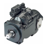
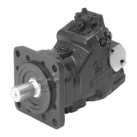
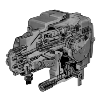
H1 Axial Piston Pump, Size 045/053, Single
Technical Information
Technical Specications
For denitions of the following specications, see Basic Information 11062168, Operating
parameters.
Technical Specications
General speci cations
Design Axial piston pump of cradle swashplate design with variable displacement
Direction of rotation Clockwise, counterclockwise
Pipe connections
Main pressure ports: ISO split ange boss
Remaining ports: SAE straight thread O-ring boss
Recommended
installation position
Pump installation position is discretionary, however the recommended control
position is on the top or at the side, with the top position preferred. If the pump
is installed with the control at the bottom, ushing ow must be provided
through port M14 located on the EDC, FNR and NFPE control. Vertical input
shaft installation is acceptable. If input shaft is at the top 1 bar case pressure
must be maintained during operation.
The housing must always be lled with hydraulic uid.
Recommended mounting for a multiple pump stack is to arrange the highest
power ow towards the input source.
Consult Sauer-Danfoss for nonconformance to these guidelines.
Auxiliary cavity pressure
Will be inlet pressure with internal charge pump. For reference see operating
parameter on next page. Will be case pressure with external charge supply.
Please verify mating pump shaft seal capability.
T000 126E
Technical data
Feature Unit Size 045 Size 053
Displacement cm
3
[in
3
] 45.0 [2.75] 53.8 [3.28]
Flow at rated (continuous) speed l/min [US gal/min] 153 [40] 183 [48]
Torque at maximum displacement
(theoretical)
N•m/bar
[lbf•in/
1000psi]
0.72 [437.7] 0.86 [522.03]
Mass moment of inertia of rotating
components
kg•m
2
[slug•ft
2
] 0.00465 [0.00343] 0.00458 [0.00338]
Mass [weight] dry (without charge
pump or auxiliary mounting
ange)
kg [lb] 41.0 [90.0]
Oil volume liter [US gal] 1.3 [0.34]
Mounting ange
ISO 3019-1 ange 101-2 (SAE B)
Special bolt diameter. See installation drawings.
Input shaft outer diameter,
splines and tapered shafts
ISO 3019-1, outer dia 22 mm - 4 (SAE B, 13 teeth)
ISO 3019-1, outer dia 25 mm - 4 (SAE B-B, 15 teeth)
ISO 3019-1, outer dia 32 mm - 4 (SAE-B, 14 teeth)
Conical keyed shaft end similar to ISO 3019-1 code 25-3, taper 1:8
Auxiliary mounting ange with metric
fasteners, shaft outer diameter and
splines
ISO 3019-1, ange 82 - 2, outer dia 16 mm - 4 (SAE A, 9 teeth)
ISO 3019-1, ange 82 - 2, outer dia 19 mm - 4 (SAE A, 11 teeth)
ISO 3019-1, ange 101 - 2, outer dia 22 mm - 4 (SAE B, 13 teeth)
ISO 3019-1, ange 101 - 2, outer dia 25 mm - 4 (SAE B-B, 15 teeth)
Suction ports ISO 11926-1 – 1
5
/
16
-12 (SAE O-ring boss)
Main port con guration
∅19.0 - 450 bar split ange boss per ISO 6162, M10x1.5
ISO 11926-1 – 1
5
/
16
-12 (SAE O-ring boss)
Case drain ports L1, L2 ISO 11926-1 – 1
1
/
16
-12 (SAE O-ring boss)
Other ports SAE O-ring boss. See installation drawings at the back of this manual.
Customer interface threads Metric fasteners
T301 001E