3
11063344 • Rev EA • Dec 2012
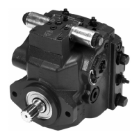
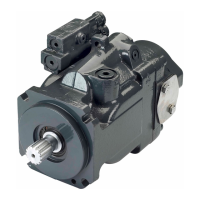
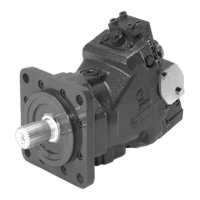
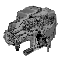
H1 Axial Piston Pump, Size 045/053, Single
Technical Information
Content
Technical Specications
General Technical
Specications
Dimensions
Charge Pump
Installation Drawings
Technical Specications ...............................................................................................................................4
Shaft Loads .......................................................................................................................................................6
Mounting Flange Loads ...............................................................................................................................7
Model Code ......................................................................................................................................................8
Electrical Displacement Control (EDC) Options A2 (12 V)/A3 (24 V) ..........................................12
Forward-Neutral-Reverse (FNR) Electric Control Options A9 (12 V)/B1 (24 V) .......................14
Non Feedback Proportional Electric Control (NFPE) Options A8 (12 V) / B8 (24 V) ..............16
Automotive Control (AC) ...........................................................................................................................18
Manual Over Ride (MOR) ...........................................................................................................................20
Displacement Limiter ..................................................................................................................................21
Input Shafts ....................................................................................................................................................22
Option G4, ISO 3019-1, ange outer dia 22 mm-4 (SAE B, 13 teeth) ....................................22
Option G5, ISO 3019-1, ange outer dia 25 mm-4 (SAE B-B, 15 teeth) ................................22
Option G1, ISO 3019-1, outer dia 32 mm-4 (SAE B, 14 teeth) ..................................................23
Option F2, ISO 3019-1, Code 25-3, Diameter 25.4 taper 1:8,
without key and no through-hole in the end of the shaft .......................................................24
Auxiliary Mounting Pads ............................................................................................................................25
Option H2, ISO 3019-1, ange 82-2 (SAE A, 9 teeth) ..................................................................25
Option H1, ISO 3019-1, ange 82-2 (SAE A, 11 teeth) ...............................................................26
Option H3, ISO 3019-1, ange 101-2 (SAE B, 13 teeth) ..............................................................27
Option H5, ISO 3019-1, ange 101-2 (SAE B-B, 15 teeth) .........................................................28
Charge Pump .................................................................................................................................................29
Port Description ............................................................................................................................................30
Dimensions .....................................................................................................................................................32
Twin port, ORB, remote lter .........................................................................................................32
Controls ......................................................................................................................................................35
Electric Displacement Control (EDC), option A2 (12 V) / A3 (24 V).................................35
Electric Displacement Control (EDC) with manual override,
option A4 (12 V) / A5 (24 V) ....... 35
Forward-Neutral-Reverse (FNR) with manual override,
option A9 (12 V) B1 (24 V) ................... 36
Non Feedback Proportional Electric Control (NFPE) with manual override,
option A8 (12 V) B8 (24V) ................................................................................................................................. 36
Automotive control (AC) with manual override, option A7 (12 V)/C2 (24 V) ...............37
Displacement limiters ...........................................................................................................................38
Displacement limiter, option B and D .......................................................................................38
Twin port, code 62 metric 4 bold FLG, option D6, D8, F2, and F3 ..................................39
Suction ltration, option L ............................................................................................................40
Remote full ow charge pressure ltration, option P for end cap option F ................41
External full ow charge pressure ltration, option E .........................................................42
Speed and Temperature Sensor, option H for mounting ange option K ...................43