30
11063344 • Rev EA • Dec 2012
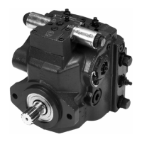
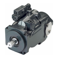
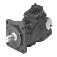
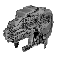
H1 Axial Piston Pump, Size 045/053, Single
Technical Information
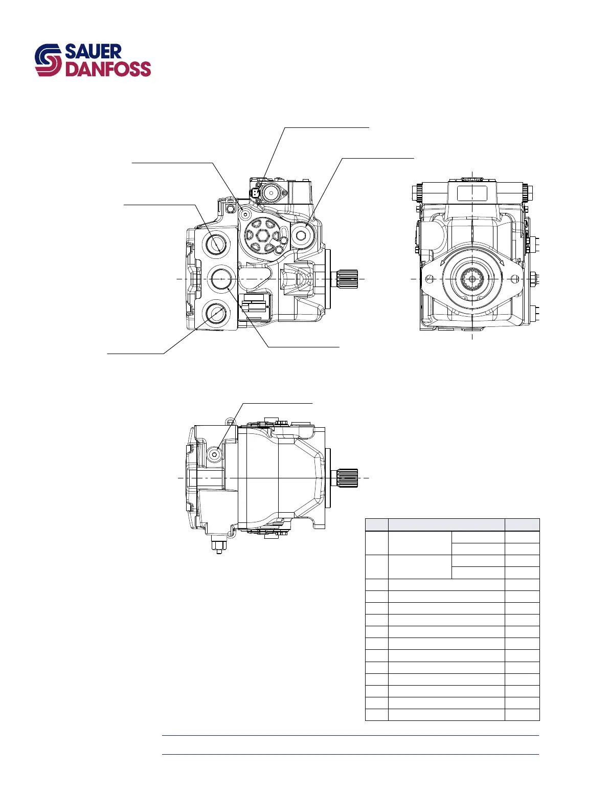
System port "B"
Port ISO 11926-1 - 1 5/16-12
System port "A"
Port ISO 11926-1 - 1 5/16-12
System A gauge port "MA"
Port ISO 11926-1 - 9/16-18
Charge inlet port "S"
Port ISO 11926-1 - 1 5/16-12
Servo gauge port "M4"
Port ISO 11926-1 - 7/16-20
∅29 max clearance dia for tting
Control solenoid connector "C2"
Deutsch DT04-2P
To be paint free
Case drain port "L4"
Port ISO 11926-1 - 1 1/16-12
CWCCW
Installation Drawings
Please contact Sauer-Danfoss for specic installation drawings
Port Description
Port description
Port Description Sizes
A
System port “A”,
optional ports
ISO 11 926-1 1
5
/
16
-12
ISO 6162 ∅19.0
B
System port “B”,
optional ports
ISO 11 926-1 1
5
/
16
-12
ISO 6162 ∅19.0
E Charge ltration port, from lter
7
/
8
-14
F Charge ltration port, to lter
7
/
8
-14
L1 Case drain port 1
1
/
16
-12
L2 Case drain port 1
1
/
16
-12
MA System “A” gauge port
9
/
16
-18
MB System “B” gauge port
9
/
16
-18
M3 Charge gauge port
9
/
16
-18
AM3 Alternate charge pressure port
9
/
16
-18
M4 Servo gauge port
7
/
16
-20
M5 Servo gauge port
7
/
16
-20
M14 Case gauge port
7
/
16
-20
S Charge inlet port 1
5
/
16
-12
T301 007E