9
11063344 • Rev EA • Dec 2012
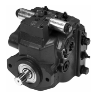
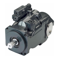
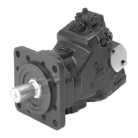
H1 Axial Piston Pump, Size 045/053, Single
Technical Information
General Technical Specications
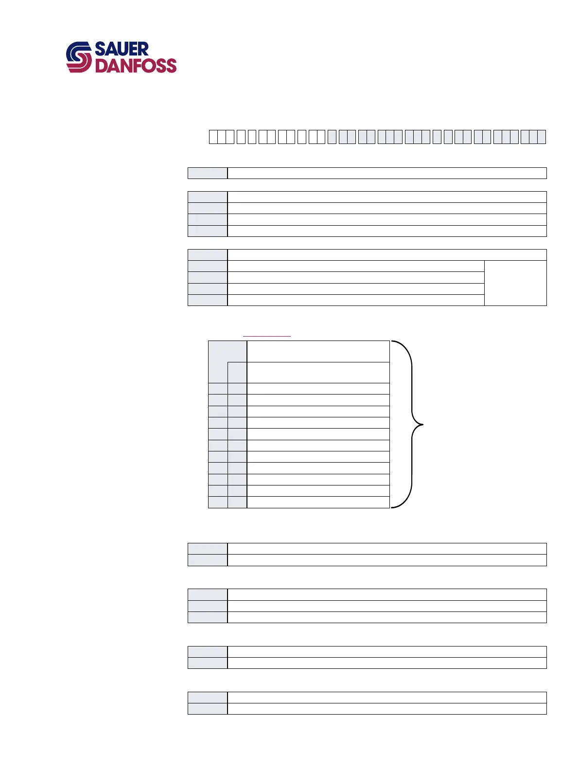
Model Code
(continued)
A B D F E G H J K M N S T V W X Y
H1 P F N N N N N N
H Mounting
F ISO 3019-1, ange 101-2 (SAE B)
J Input shaft
G4 ISO 3019-1, outer dia 22 mm - 4 (SAE B, 13 teeth splined shaft
16
/
32
pitch)
G5 ISO 3019-1, outer dia 25 mm - 4 (SAE B-B, 15 teeth splined shaft
16
/
32
pitch)
G1 ISO 3019-1, outer dia 32 mm - 4 (SAE B, 14 teeth splined shaft
12
/
24
pitch)
F2 Conical keyed shaft end similar to ISO 3019-1 code 25-3, taper 1:8 (key not supplied with pump)
K Auxiliary mounting pad
NN None
H2 ISO 3019-1, ange 82 - 2, outer dia 16 mm - 4 (SAE A, 9 teeth
16
/
32
coupling)
Shipping cover
H1 ISO 3019-1, ange 82 - 2, outer dia 19 mm - 4 (SAE A, 11 teeth
16
/
32
coupling)
H3 ISO 3019-1, ange 101 - 2, outer dia 22 mm - 4 (SAE B, 13 teeth
16
/
32
coupling)
H5 ISO 3019-1, ange 101 - 2, outer dia 25 mm - 4 (SAE B-B, 15 teeth
16
/
32
coupling)
M Overpressure protection type and setting side “A” **
N Overpressure protection type and setting side “B” **
** Pressure protection type must be the same for side “A” and “B”
L
High pressure relief valve + pressure
limiters with bypass
Use the selection for ports “A” and “B”
K
High pressure relief valve only with bypass
(no pressure limiters)
L18 K18 180 bar [2610 psi]
L20 K20 200 bar [2900 psi]
L23 K23 230 bar [3336 psi]
L25 K25 250 bar [3630 psi]
L28 K28 280 bar [4061 psi]
L30 K30 300 bar [4350 psi]
L33 K33 330 bar [4786 psi]
L35 K35 350 bar [5080 psi]
L38 K38 380 bar [5510 psi]
L40 K40 400 bar [5800 psi] (45 cm
3
only)
L42 K42 420 bar [6090 psi] (45 cm
3
only)
Contact factory for pressures not shown or for applied pressure above maximum working pressure
(see System Pressure page 5)
S Charge pump
B 12 cm³/rev [0.73 in³/rev]
N No charge pump, external charge supply, (align with Option T: Filtration Options, option E)
T Filtration options (align with option G: Endcap selection)
L Suction ltration (see basic drawings)
P Remote full charge ow ltration (see endcap drawings)
E External charge ow ltation (see endcap drawings), (align with option S: Charge pump, option N)
V Charge pressure relief setting (contact factory for pressure not shown)
20 20 bar [290 psi]
24 24 bar [348 psi]
W Special hardware features
PN None
P1 NFPE valve plate (align with option D: Control Selection and option E: Displacement Limiters)