Other
OPM 100 en-GB 96
© Scania CV AB 2023, Sweden
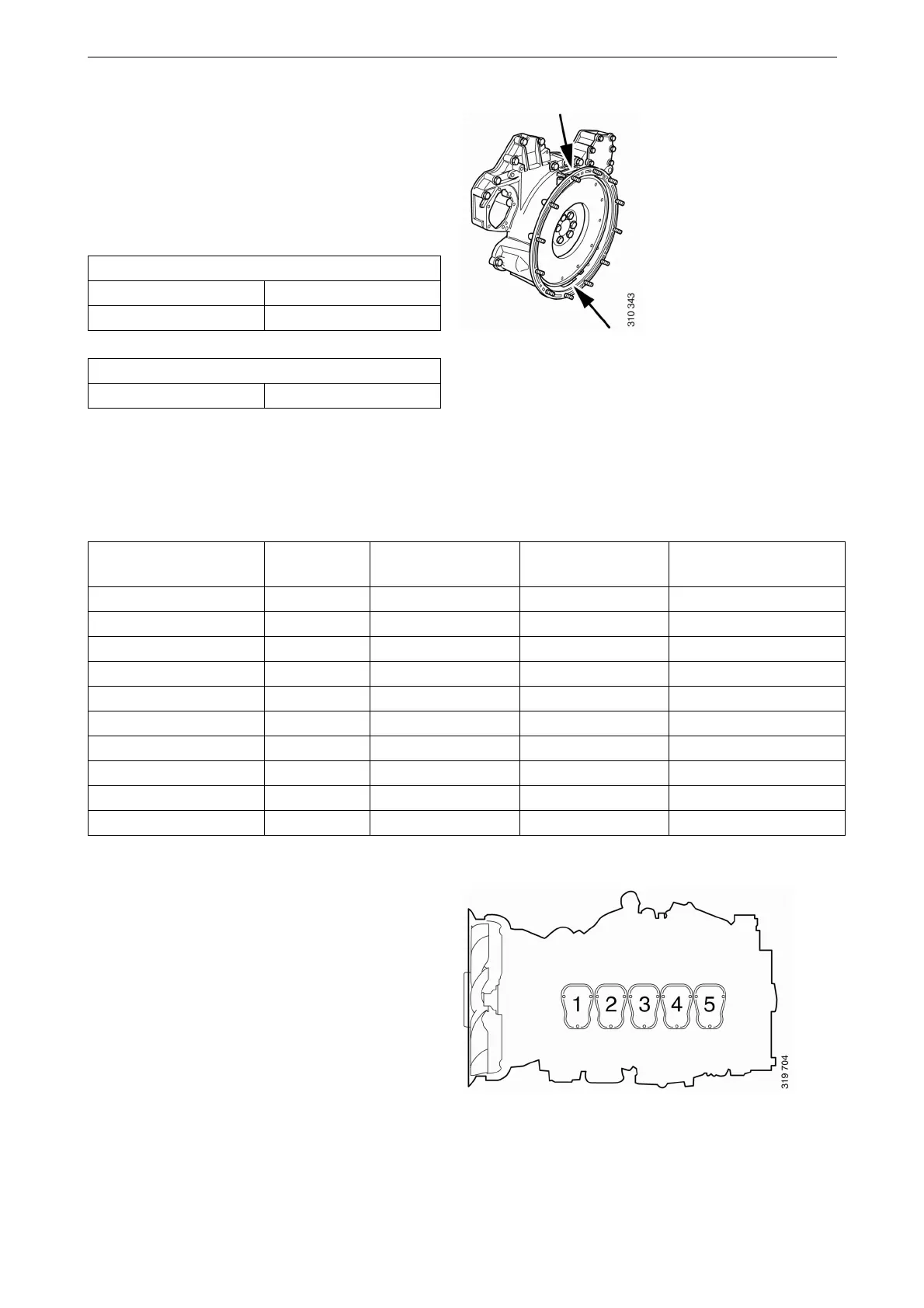
The reference information UP TDC,DOWN
TDC and the angle indications listed in the table
below are engraved on the flywheel. Depending
on the engine installation, this information is vis-
ible in one of the windows, either furthest up or
furthest down on the flywheel. See illustration.
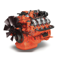
Adjust the valves according to the table below.
Follow the respective column depending on
whether you are reading the engraving on the fly-
wheel in the lower or the upper window. Start ad-
justment at the top of the table.
Valve clearance, specifications
Intake valve 0.45 mm (0.018 in)
Exhaust valve 0.70 mm (0.028 in)
Tightening torque
Lock nut for valves 35 Nm (26 lb/ft)
Reading in the lower
window
Rotation Valve transition on
cylinder
Adjust valves on
cylinder
Reading in the upper
window
DOWN TDC 1 1 UP TDC
72/432 1 5 252/612
144/504 1 2 324/684
216/576 1 3 36/396
288/648 1 4 108/468
DOWN TDC 2 1 UP TDC
72/432 2 5 252/612
144/504 2 2 324/684
216/576 2 3 36/396
288/648 2 4 108/468
Upper and lower window to read the engraving on
the flywheel.