19 slant scale
20 intake slit
21 carrying handle
Assembly
Warning: For your own safety, connect the machine to the
power source only after all of the of the steps to assemble
the machine have been completed and you have read and
understood the operating instructions with all of their safety
and operating notes.
Note: Organize all of the parts that you need for the assem-
bly before you begin. Note the assembly instructions and
follow them carefully with the help of a second person.
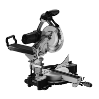
Freeing the Intake Slit (fig. 2)
After the saw has been removed from the package, release
the blocking knob of the intake slit (1). When the mitre box
saw is being transported or stored the intake slits must al-
ways be blocked. The slit block knob (1) is on the right side
of the slit.
Assembling the Hand Grip (fig. 1)
Thehandgrip(9)onthefrontsidemustbeturneduntil
it is tight.
Assembly of the Dusk Bag (fig 4)
• Inordertoinstallthedustbag(1),pressthemetalcollar
wings(2)together.
• Placethecollaropeningofthedustbagonthedustsup-
ports(3)andreleasethemetalcollarwings.
Assembly of the Screw Vice (fig. 5)
• Placeaknuriedscrew(1)onthebackofthemachine
body, one for each side.
• Placethescrewvice(2)intheprepareddrillholeson
the body.
Saw Blade Key (fig. 6)
Forpracticalstorageandtopreventlossofthekey,thereis
aclipforitontherightsideoftheintakeslit.
Note: We strongly recommend that this crown and mitre
boxsawbe ttedsecurelyonaworkbench, sothatyour
machineisasstableaspossible.
• Findandmarkthefourplacesontheworkbenchwhere
holes are to be drilled.
• Drilltheholesintothebenchwitha¿10mmbit.
• Screwthecrownandmitreboxsawwithscrews,wash-
ers and nuts securely onto the bench. Please be aware
thatthesefasteningelementsarenotsuppliedwiththe
machine.
Start Up
Note: This machine was precisely adjusted before leaving
the factory. Check the precision and adjust it if necessary
in order to achieve the best operating results (see also the
section on corrective measures).
Tool operation
WARNING! Never connect the machine to a power source
before all installation and positioning has been completed
and you have read and understood the safety and operating
instructions.
Basic Operation of the Crown and Mitre Box Saw with Intake
Function
• Always use a screw vice to hold the materials tightly.
There are two holes on the machine to secure the screw
vice(g.5).
• Alwayspositionthematerialsonthesurfacearea.Any
twisted or crooked materials which cannot lie flat on the
table or the surface area can get caught in the saw blade
and should not be used.
• Neverputyourhandsintheareaofthesaw.Keepyour
handsatalltimesoutsideofthe„ForbiddenHandArea,“
which includes the entire mounting table. This area has
a„NoHands“sign.
Warning: In order to avoid accidents resulting from materi-
alsthatyoutofthemachine,theplugmustbetakenout
ofthesocketandthenthesmallpiecesremoved.
Tounlockthesawheadwhenitisinatiltedposition:
• Pushthesawhead(1)andtheblockinglever(4)gently
downward.
• Pulloutthespringchock(2).
• Bringthesawheadintothefullyuprightposition.
Switching on the Saw (fig. 15)
Pushthesafetygrip(1)downwardandpushtheswitch(2)
to switch on the saw.
Straight Cut (fig. 16)
• Tomakeastraightcutinasmallpieceofmaterial,push
thecompletesawheaddownandpullopentheslitblock
grip(1).
• Tosawthickerboards(upto305mm),theslitblockgrip
must be released so that the saw head can move freely.
• Placethematerialstobecutonthetable,ushagainst
the chock. Use the screw vice that is attached to the
bodyofthemachinewheneverpossible.
• Push thesafety lever(5)downward andpressthe on/
offswitch(3)toswitchonthesaw.Movethebladeby
meansofpressingthegrip(4)downwardintothemate-
rialwithaslowandsteadypressure.
• Whenthecutiscomplete,presstheswitchandletthe
saw blade come to a full stop before raising the saw
head.
Bevelled Cuts (fig. 17)
Thismachineisequippedwithtenbevellingsprings(1)on
thebody.Theyareplacedat0,15,22.5,31.6and45de-
grees to the left and right as well as 60 degrees to the left.
Thesesettingscorrespondtothemostoftenusedbevelled
cuts. Here is how you make a bevelled cut:
• Release the bevelled montage table by lifting up the
quickrelease(2).
• Asyouraisethespringgrip(3),grabthehandgrip(4)
and turn the montage table to the left or right to the
desired angle.
• Lockthespringgripintothedesiredangle.
Note: The lever can only be locked into one of the ten
lockingpositions.
• Once the desired bevelling angle has been reached,
pressthebevelmontagetabledowninordertoxthe
position.
• Shouldthedesiredbevellinganglenotbeoneoftheten
presets,simplyadjustthetabletothedesiredangleby
pushingthebevellingmontagetable(2)releasedown.
Slanted Cuts (fig. 18, 19)
Warning: Inordertoproduceslantedcutsthebladeposi-
tion must be fully brought to the left or right. Otherwise
there is not enough room for the saw blade to be carried all