the way through and this can lead to serious injuries. For
extreme bevelled or slanted cuts the saw blade can also be
run against the chock.
Adjustthe saw head with the tommy screw (2). Tilt the
saw head to the desired angle as shown on the slanting
scale.Thebladecanbepositionedatanyanglefroma90°
straightcut(0°onthescale)to45°tiltedeithertotheleft
ortheright.Inordertoadjustthepositionofthesawhead,
setthefasteninglever(1)totherightpositionbypushing
itdown.Therearepositivepositionpresetsforinclinations
of0°,33.9°und45°available.
Note: A chock peg for the 33.9° is included to produce
„crown“cuts.
Multiple Cuts (fig. 19)
• Extendthebladechockasfarasitwillgo.
• Establishthedesiredangleofslantusingthefastening
lever(1).
• Establishthedesiredbevellingangleandadjustit.See
the section on bevelled cuts.
Basis Form Cuts (fig. 20)
Basisformscanbemadevertically,againstthechock,or
flat on the mounting table. Follow the table.
Note: Forspecialceilingmoldingsthismachinehasapar-
ticularchockataslantof33.9°preset.Shouldthisangle
bedesired,thensimplypushthechocklever(4)intothe
slitandpositiontheslantat33.9°(g.9).
Combination Cuts
• Acombinationcutisacombinationofabevelledand
slanted cut. For this cut use the instructions above.
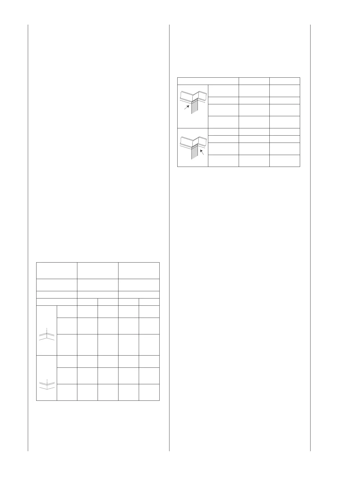
Floorboards
• Floorboardscanbecutverticallytothetablesurfaceor
atonthetable.Consultthefollowingtable.
Setting Verticalsetting(board
is flat on the mounting
board)
Horizontalposition
(boardreverseisaton
thetable)
Extension area Neartosawblade Distance to the saw
blade
Slant angle 0° 45°
Boardposition left side right side left right
Interior
corner
Bevel
angle
45°/0°
/45°
45°right 0° 0°
Board
position
Lower
side on
the table
Lower
side on
the table
Upper
side on
the chock
Underside
on the
chock
Complet
ed side
Make the
cut left of
the mark
Make the
cut right
of the
mark
Make the
cut left of
the mark
Make the
cut left of
the mark
Exterior
corner
Bevel
angle
45°right 45°/0°
/45°
0° 0°
Board
position
Lower
side on
table
Lower
side on
table
Lower
side on
the chock
Upper
side on
the chock
Complet
ed side
Make cut
right of
marking
Make cut
right of
marking
Make cut
right of
marking
Make cut
right of
marking
Ceiling Moldings (fig. 20, 21)
• Ceilingmoldingscanonlybemadewiththecrownand
mitre box saw flat on the table.
• Thiscrownandmitreboxsawhasaparticularbevelled
chockfor33.9°especiallyforceilingmoldings,thatis
betweenthebackoftheboardandtheceiling,placedon
theupper,smoothsurfacewithanangleof52°;between
the back of the board and the wall on the lower, flat side
there is an angle of 38°. For the cuts necessary for such
aceilingmolding,pleaseconsultthefollowingtable.
Note: This special cut cannot be used with a ceiling molding
of 45°.
• Sincemostroomsdonothaveanexact90°angle,ne
adjustments may be necessary. Always make a test cut
to be sure that the angle is correct.
Setting Left Side RightSide
InternalCorner
Bevelledangle 30° from the
right
30° from the left
Slanting Angle 33,9° 33,9°
Boardposition Uppersideof
the surface
Lower side of the
surface
Completedside Cutleftofthe
marking
Cutleftofthe
marking
ExternalCorner
Bevelledangle 30° von links 30° von links
Slanting Angle 33,9° 33,9°
Boardposition Lower side of the
surface
Uppersideof
the surface
Completedside Cutrightofthe
marking
Cutrightofthe
marking
Automatic Intake (fig. 22)
Warning: The operator must never pull the saw head toward
him or herself during operation. The blade could draw the
upper side of the material upward and cause recoil of the
saw head with its blade.
• Never push the running blade down, until the saw head
has been drawn to the upper side of the sawed material.
• Pullthechockout.
• Releasetheslitblockinggrip(1)sothatthesawhead
can move freely.
• Setthedesiredslantangleandorbevelangleandlock
it in.
• Whenmakingaslantedcut,placetheleftaswellasthe
rightslicingchocksintheoperationalposition.
• Useascrewvicetosecurethematerials
• Graspthesawgrip(3)andpulltheslits(4)forwarduntil
the middle of the saw blade is above the front side of the
material(5).
• Pullontherelease(6)tostartthesaw.
• Whenthesawhasreacheditsfullspeed,pressthehan-
dlesslowlydownthroughtheupperedgeofthemateri-
als.
• Movethehandlesslowlyagainstthechockandbringthe
cut to an end.
• Usethereleaseandletthebladerundownbeforemov-
ingthesawheadup.
Setting the Cut Depth (fig. 23)
For straight and flat repeated cuts the cut depth can be set
in advance.
• Movethesawheaddownuntilthesawbladeteethhave
reachedthedesiredcutdepth.
• Whileholdingtheupperarminposition,turnthestop
knob(1)untilithasreachedthestopplate(2).
• Checkthedepthof theteeth andmove thesaw head
fromthefronttothebackthroughthefullareaofatypi-
cal cut along the steering arm.
Wave-laser Management
Yourmachineis equippedwithourlatestdevelopment
thelasermanagement,abatteryoperateddevicethatuses
laser beams of the class IIIa category. The laser beams
makeitpossibleforyoutopredictthelengthofabevelcut
on the materials before you begin sawing.