GF3000 SERIES INSTALLATION MANUAL
Installing a GF3000 Series Lock
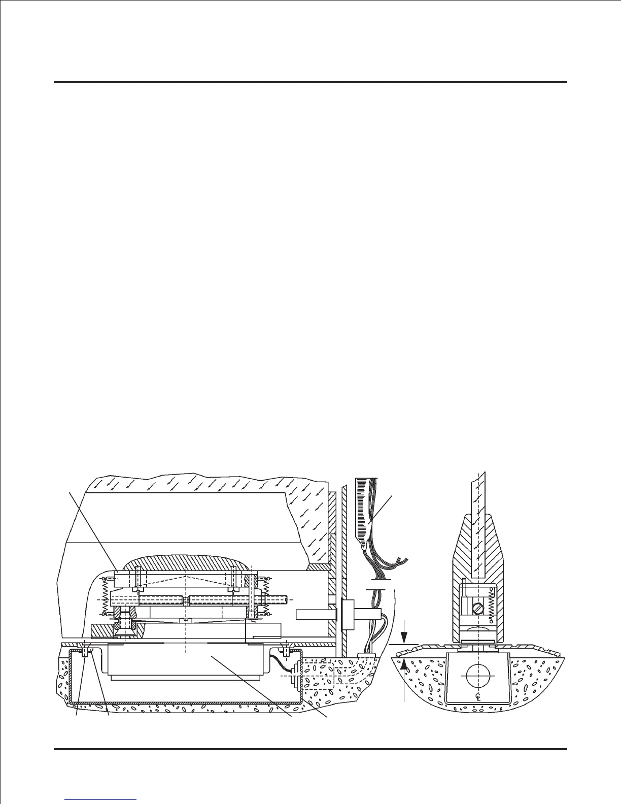
5) Mounting the GF3000BRD Magnet Into the Threshold Box:
a
e
d
b
c
1/2 ref
• Mount magnet (a) to box (b) by placing two speed nuts (c) per slot, side by side in
flanges of box.
• Line up magnet over speed nuts. Insert #10-24 x 1/2" flat head screws (d) into
magnet brackets and through speed nuts.
Align magnet, making sure centerlines of
armature are on the centerlines of magnet. Tighten screws.
• If needed, add shims under magnet to bring magnet flush with top of threshold.
NOTE: Top surface of magnet must not protrude above top surface of threshold.
• Replace door on hinges.
• Adjust armature, using adjusting screw located in access hole so that the clearance
gap of approx. 1/16" between magnet face and armature is achieved. It may be
necessary to slightly re-adjust the gap to achieve proper locking action and spring
return action when the magnet is de-energized.
• If door’s bottom rail depth is greater than 1-3/4", spacers (e) may be needed
(one, 1/8" thick spacer is supplied).
• Install door status switch into frame and actuating magnet into door (see Door
Status Monitor (DSM) - GF3000BRD on page 23.).
• After all magnet adjustments have been completed, it is strongly recommended to
fill the magnet box with a spray urethane foam insulation (available from most
building supply companies) to keep water out.
• Make final wiring connections (see Wiring Diagram: on page 22.
NOTE: Mount Control Module (f) in a remote and dry location, and no more than 15
feet away from lock.
f
Page 16