GF3000 SERIES INSTALLATION MANUAL
Installing a GF3000 Series Lock
Installing a GF3000 Seri es Lock
Preparing the Frame and Door
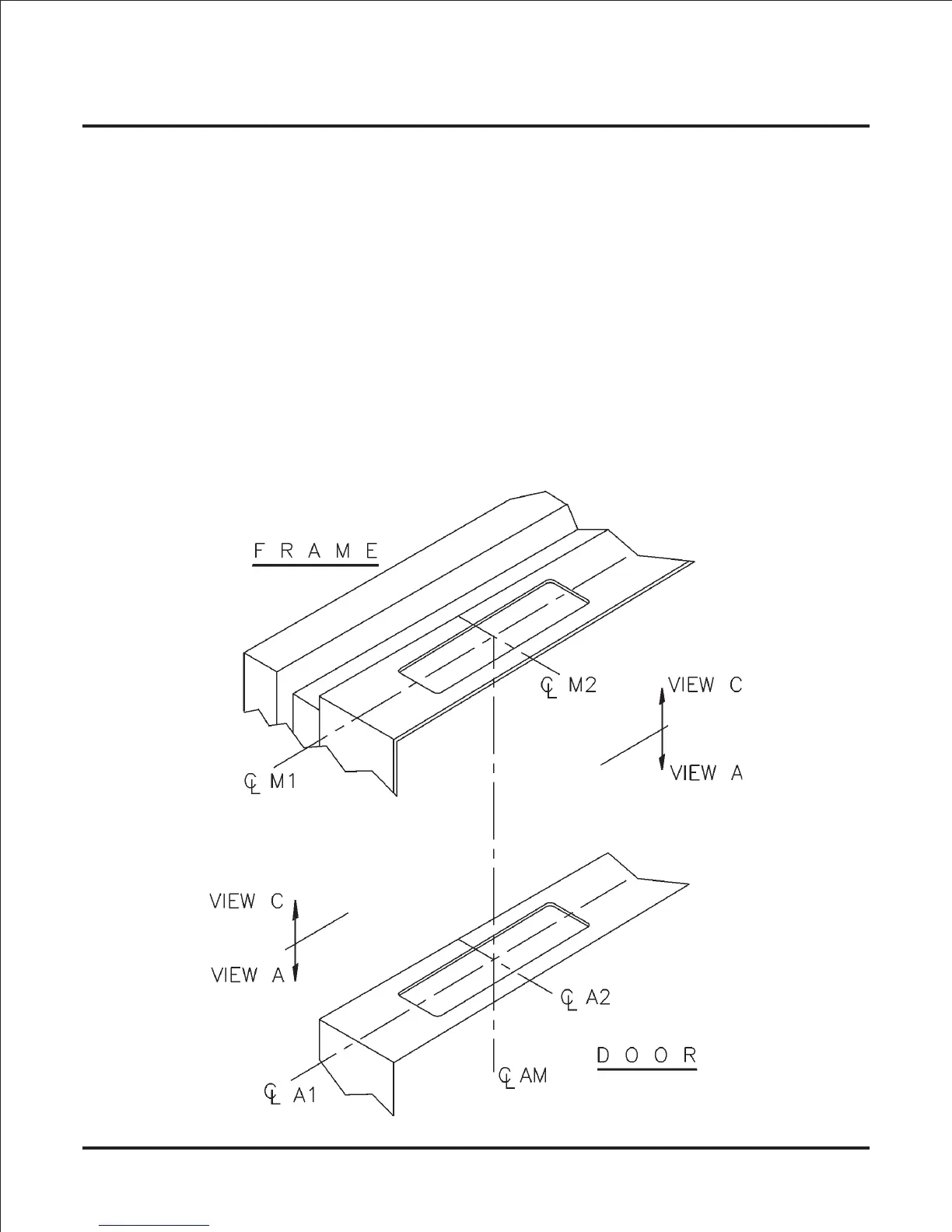
1) Establish Frame and Door Centerlines (Standard and TRD):
• For proper operation, it’s critical to establish centerlines of magnet and armature assembly
that line up to form a vertical axis. The figure below shows the centerline scheme for a stan-
dard GF3000 and a GF3000TRD. Note that centerlines for magnet (M1 and M2) are directly
above centerlines for armature assembly (A1 and A2) thus forming a vertical axis (AM).
• Check door & frame for any structural member or hardware component that might interfere
with magnet and armature mounting areas before selecting template location.
• Remove existing hung doors for template application and armature installation.
• The standard model GF3000 can be installed in a horizontal or vertical configuration.
• To achieve maximum resistance to forced entry, position as follows:
> Horizontal configuration - position unit closest to the latch side of door.
> Vertical configuration - positioning unit closest to the strike plate is recommended.
• In some applications, the door and frame may require reinforcement.
Page 6