GF3000 SERIES INSTALLATION MANUAL
Installing a GF3000 Series Lock
Wiring the Lock-Standard, TRD, TJ, SM
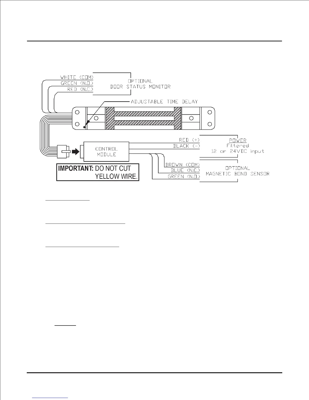
1) Wiring Diagram:
2) Standard Features:
Operating Voltage
The GF3000 will operate only on filtered and regulated 12 or 24 volts DC. Automatic
voltage selection circuitry is standard, eliminating the need for a voltage selection switch.
Automatic Relock Switch (ARS)
A built-in relock switch requires the door to be in the closed position before the magnet
can be energized.
Adjustable Time Delay (ATD)
The ATD provides a time delay to relock that is adjustable from 2 to 30 seconds.
The unit has been preset at the factory for a 3 second relock delay.
3) To Adjust Relock Time Delay:
1) Refer to the wiring diagram above and note location of ATD arrow.
2) With door open, apply power.
3) Remove 5/64” hex head screw to allow access to recessed momentary pushbutton switch.
4) Using the hex wrench provided, depress and release the recessed switch one time for each
second of delay required (max. =30 seconds/min.=2 seconds).
Example
: To set ATD to 5 seconds, depress the recessed switch 5 times.
NOTE: If a mistake is made, wait 10 seconds, then repeat Step #4.
5) Reinstall hex head screw, after setting desired relock time delay.
6) Close door and verify delay.
Page 17