GF3000 SERIES INSTALLATION MANUAL
Installing a GF3000 Series Lock
Wiring the Lock - BRD
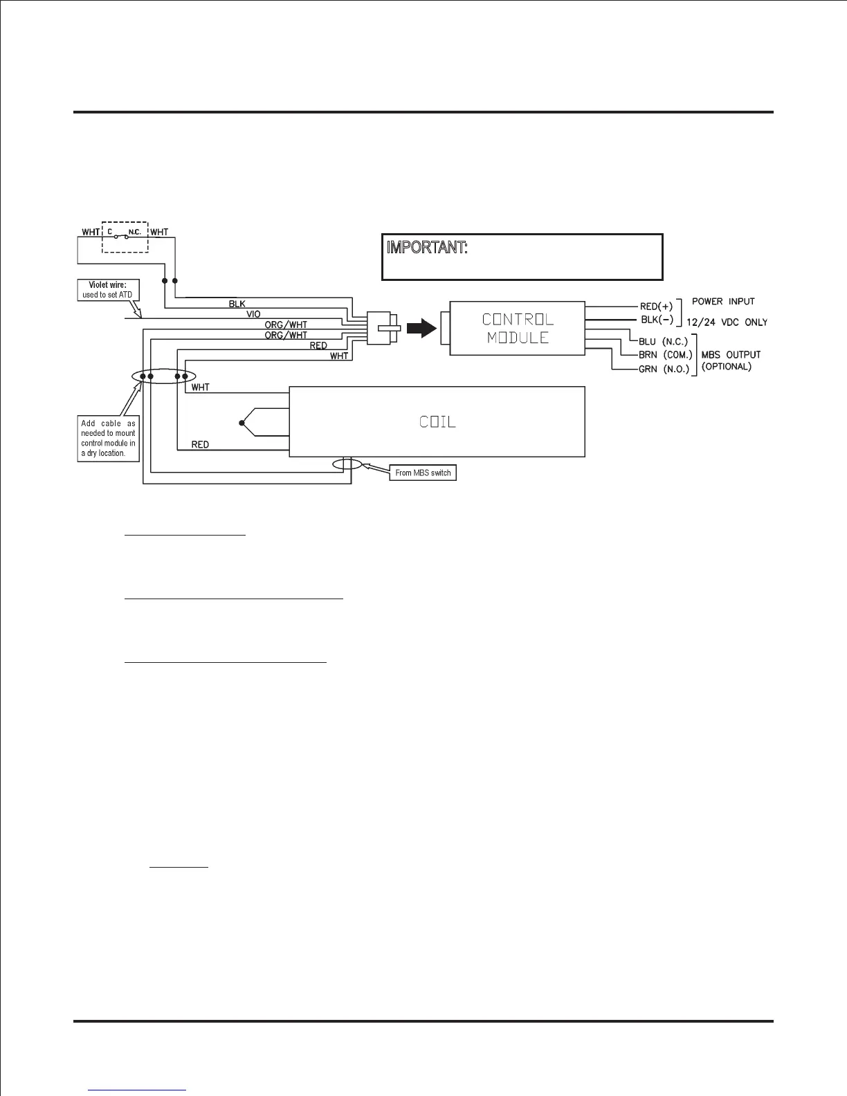
1) Wiring Diagram:
2) Standard Features:
Operating Voltage
The GF3000BRD will operate only on filtered and regulated 12 or 24 volts DC. Automatic
voltage selection circuitry is standard, eliminating the need for a voltage selection switch.
Automatic Relock Switch (ARS)
A built-in relock switch requires the door to be in the closed position before the magnet can
be energized.
Adjustable Time Delay (ATD)
The ATD provides a time delay to relock that is adjustable from 2 to 30 seconds.
The unit has been preset at the factory for a 3 second relock delay.
3) To Adjust Relock Time Delay:
1) Verify that the exposed yellow wire on the ARS is not shorting against anything.
2) With door open, apply power.
IMPORTANT: Do not cut yellow wire.
3) Touch the violet wire to the black ARS wire one time for each second of delay required
(maximum = 30 seconds, minimum = 2 seconds).
Example
: To set ATD to 5 seconds, touch the violet wire to the black ARS wire 5 times.
NOTE: If a mistake is made, wait 10 seconds, then repeat Step #4.
NOTE: A pushbutton switch may be used if desired.
4) Properly insulate the violet wire after setting desired relock time delay.
5) Close door and verify delay.
6) If OK, permanently connect and insulate the yellow wire on the ARS.
YEL
Automatic Relock Switch (ARS)
Page 18
DO NOT CUT YELLOW WIRE
ON CONTROL MODULE.
IMPORTANT:
FILTERED, REGULATED
YEL