GF3000 SERIES INSTALLATION MANUAL
Installing a GF3000 Series Lock
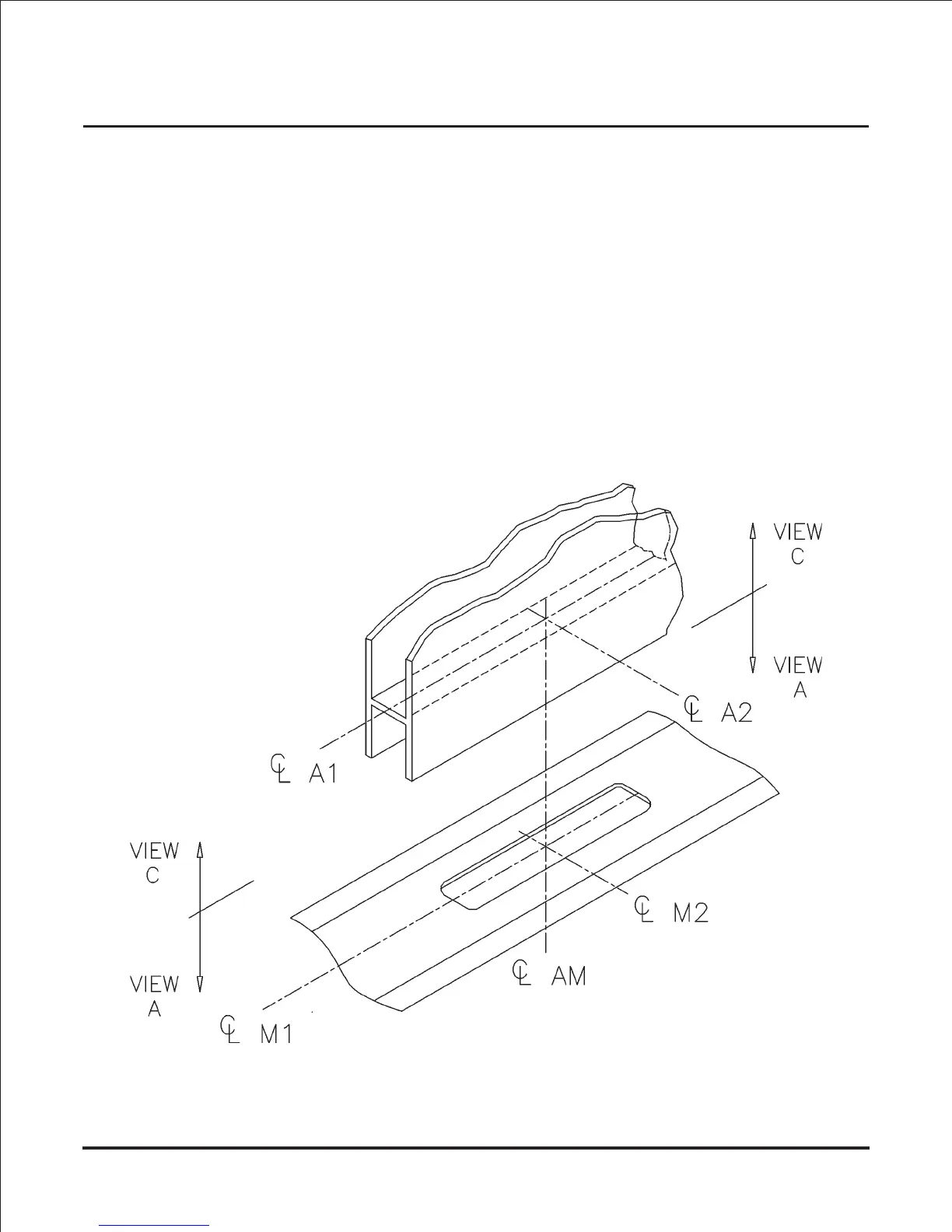
1) Establish Frame and Door Centerlines (BRD):
• For proper operation, it’s critical to establish centerlines of the magnet and armature
assembly that line up to form a vertical axis. The figure below shows the centerline scheme
for a GF3000BRD. Note that centerlines for magnet (M1 and M2) are directly below
centerlines for armature (A1 and A2) thus forming a vertical axis (AM).
• To achieve maximum resistance to forced entry, position unit closest to latch side of door.
• Adjusting screw must be accessible with a long bladed screwdriver when door is hung.
• Check both door & frame for any structural member or hardware component that
might interfere with magnet and armature mounting areas before selecting
template location.
• Existing hung doors will normally have to be removed for template application
and armature installation.
• In some applications, the door and frame may require reinforcement.
Page 7