Assembly
14.00 | SRU | Assembly and Operating Manual | en | 389439 23
Further information on the hose-free direct connection contains
the catalog data sheet.
5.3 Settings
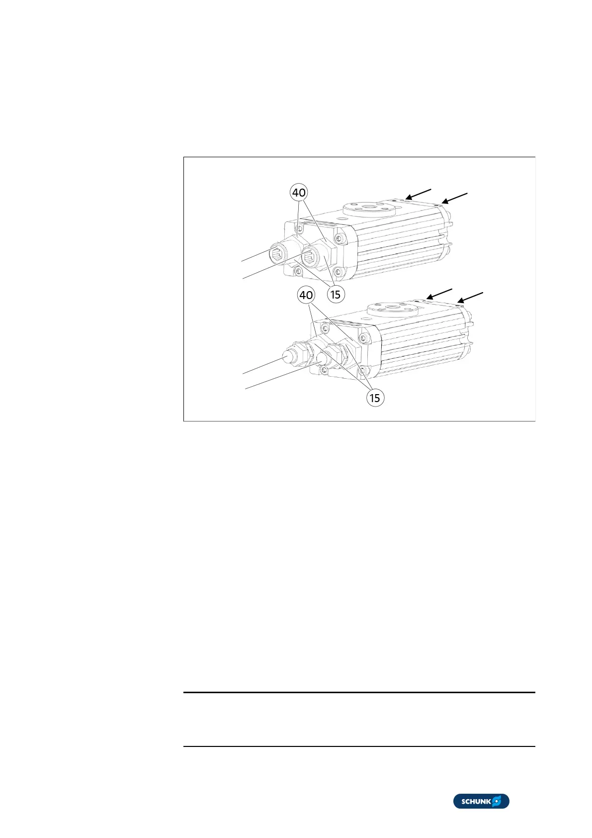
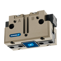
5.3.1 Adjustment of the end positions
Stop A
Stop B
Connection B
Connection A
Connection A
Connection B
Stop A
Stop B
Variant W
Variant H or variant S
Adjustment of the end positions
1. Apply pressure to connection A until the rotary unit has
reached its end position.
2. Loosen the lock nut (40) at stop B.
3. Set the end position with sleeve B (5) and stop B (15).
4. Hold sleeve B (5) and stop B (15) tight and tighten the lock
nut (40).
5. Check the end positions.
6. Apply pressure to connection B until the rotary unit has
reached its end position.
7. Loosen the lock nut (40) at stop A.
8. Set the end position with sleeve A (5) and stop A (15).
9. Hold sleeve A (5) and stop A (15) tight and tighten the lock nut
(40).
10. Check the end positions.
NOTE
When the lock nut (40) is loosened, air can escape at the sleeve
(5) and at the stop (15). This is due to the design and is normal.