Assembly
14.00 | SRU | Assembly and Operating Manual | en | 389439 27
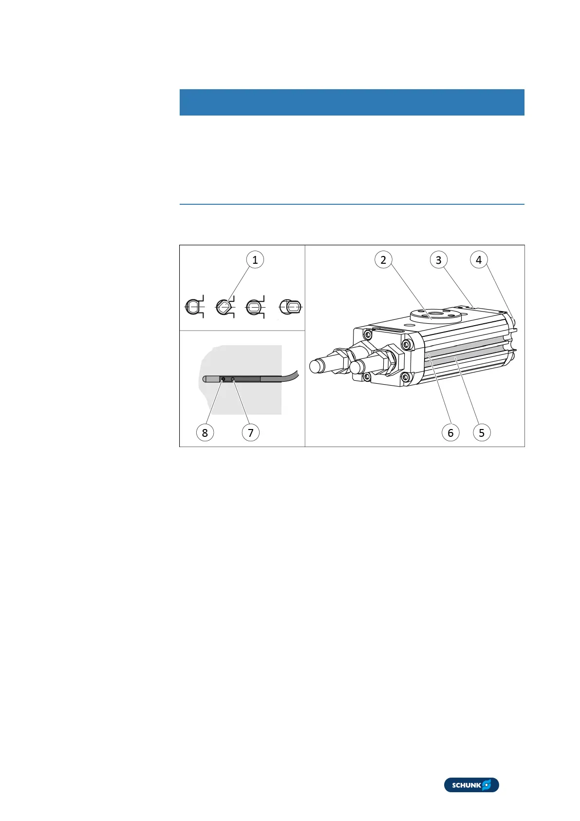
5.4.3 Mounting MMS 22-PI1 programmable magnetic switch
CAUTION
Material damage due to an incorrect tightening torque!
If the threaded pin is tightened with an incorrect tightening
torque, the product may be damaged.
l
Observe a maximum tightening torque of 10 Ncm for the set-
screws.
Two groves have been worked into the housing to mount the
sensors.
1. Connect sensor and secure cable, see the Sensor Assembly
and Operating Manual.
2. Apply air pressure to connection "A" (4).
ð Pinion (2) swivels towards the end position.
3. Hold teaching tool to the sensor (1) until the sensor flashes.
4. Insert or screw the sensor (1) into the groove (5), until the
sensor flashes rapidly.
5. Tighten set screw (8).
ð Tightening torque: 10Ncm
6. Bleed connection "A" (4).
7. Actuate connection "B" (3).
ð Pinion (2) swivels into the other end position.
8. Repeat steps for the second sensor.
9. Check the switching position and test its function.
Center position
variant
Rotate unit in the center position and mount sensor analogously.