Table of contents
4
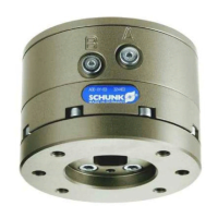
10.00 | SWS 005 – 300 | Assembly and Operating Manual | en | 389456
5 Assembly ................................................................................................................22
5.1 Example of mounting ......................................................................................... 22
5.2 Interface Plate Design and Mounting................................................................. 23
5.3 Requirements of the storage magazine ............................................................. 24
5.4 Mechanical connection ...................................................................................... 27
5.4.1 Fastening of the quick-change head (SWK) ............................................27
5.4.2 Fastening the quick-change adapter (SWA) ...........................................28
5.4.3 Tightening torque ...................................................................................28
5.5 Pneumatic connection........................................................................................ 31
5.6 Valve Requirements and Connections................................................................ 32
5.7 Pneumatic plan................................................................................................... 32
5.8 Sensors - Piston Stroke Control .......................................................................... 33
5.8.1 Piston Stroke Control of the piston with SIP-plate .................................33
5.8.2 Piston Stroke Control integrated in the body.........................................34
5.8.3 Typ Lock and Unlock Sensors..................................................................35
5.9 Optional Module Installation.............................................................................. 36
5.9.1 Electrical Module Installation E10/E20 - SWS-005 and SWS-011 ..........36
5.9.2 Electrical Module Removal E10/E20 - SWS-005 and SWS-011 ...............36
5.9.3 SWK Electrical Module Installation A15/B15 - SWS-005 and SWS-011...... 37
5.9.4 SWA Electrical Module Removal E10/E20 - SWS-005 and SWS-011 ......37
5.9.5 Flat A Optional K Series Module Installation - SWS-020 and SWS-021 ...... 38
5.9.6 Flat A Optional K Series Module Removal - SWS-020 and SWS-021 ......39
5.9.7 Flat B Optional Module Installation - SWS-021 ......................................39
5.9.8 Flat B Optional Module Removal - SWS-021 ..........................................40
6 Operation ...............................................................................................................41
6.1 Conditions for Coupling ...................................................................................... 41
6.2 Fail-Safe Operation............................................................................................. 42
6.3 Conditions for Uncoupling.................................................................................. 43
7 Trouble shooting.....................................................................................................44
7.1 Quick-change head (balls) doesn’t move ........................................................... 44
7.2 Quick-change head doesn't clamp the quick-change adapter correctly ............44
7.3 Clamping force between quick-change head and quick-change adapter is
reducing.............................................................................................................. 44