Maintenance and Care
54
10.00 | SWS 005 – 300 | Assembly and Operating Manual | en | 389456
Ø Using a 0.9mm allen wrench, secure the new sensor to the SWK
with the socket set screw. Tighten to 0.08Nm.
Ø Connect to the M8 end cable connector of the sensor. When
power is turned on to the sensor LED should be illuminated and
sensor signal should be ON.
Ø Connect other utilities to the optional modules on the SWK.
Ø Confirm the operation of the replaced sensor.
✓ Provide Lock or Unlock air to the SWS.
✓ Verify the corresponding sensor signal is ON and the sensor
LED is illuminated.
Ø After the procedure is complete, resume normal operation.
8.4.4 Lock and Unlock Sensor Assembly Replacement (with Sensor
Assemblies for SWS 040Q, 046, 076, 110, 160)
Ø Depending on the robot and interface plate used, the SWK may
have to be removed.
Ø Disconnect the Lock and/or Unlock sensor cable connectors
from the Lock and/or Unlock sensor.
Ø Remove the two M3 socket head cap screws that secure the
Lock and/or Unlock sensor to the SWK body.
Ø Pull the sensor straight out from the SWK body.
Ø Discard the removed sensor.
NOTICE
The Lock and Unlock sensor assemblies are precision aligned
and permanently assembled at the factory.
• Do not attempt to disassemble and rebuild.
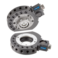
Unlock Sensor
M3 Socket
Head Cap Screws
Lock Sensor