Maintenance and Care
10.00 | SWS 005 – 300 | Assembly and Operating Manual | en | 389456
57
8.5.1 Seal Inspection and Replacement for Electrical Modules
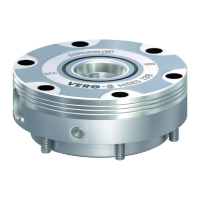
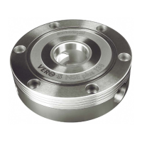
V-Ring Seal
V-Ring Seal
Stretch seal over shoulder
of pin block and push
seal hub down against the
pin block with finger tip
Pinch edge of seal with
fingers and gently pull
away from pin block
The seal protects the electrical connection between the SWK and
SWA. If the seal becomes worn or damaged it needs to be
replaced.
Ø To remove the existing seal, pinch edge of seal with fingers and
gently pull the seal away from the pin block on the SWK.
Ø Pull the seal off the pin block.
Ø To install a new seal, stretch the new seal over the shoulder of
the pin block.
Ø Push the seal’s hub down against the pin block using finger tip.
8.6 Alignment Pins
Alignment pins are the tapered pins located on the face of the
SWK that guide theSWK and SWA together during the locking
process. In heavy-duty applications, alignment (locating) pins
Assembly drawings [
}
62] may need to be replaced due to wear.
When replacing alignment pins always use original SCHUNK parts.
8.6.1 Replacemanent - SWS 005 / 011 /007
Excessive alignment pin/bushing wear could indicate poor robot
positioning during pickup/drop- off. Adjust the robot position as
needed. Check the tool stand for wear and alignment problems. If
necessary, replace the alignment pins.
Ø Place the SWS in a secure location.
Ø Uncouple the SWK and SWA.
Ø Turn off and de-energize all energized circuits (e.g. electrical,
air, water, etc.).
Ø If the M3 socket head cap screw cannot be accessed from the
tool side of the SWA, remove the SWA from the customer
tooling.