Operation
Startup 250:Users:Danny:Desktop:Operation manuals:line pumps:maverick
(P305):pHseriesOPERATION.fm
33
Operation Manual - SP 305
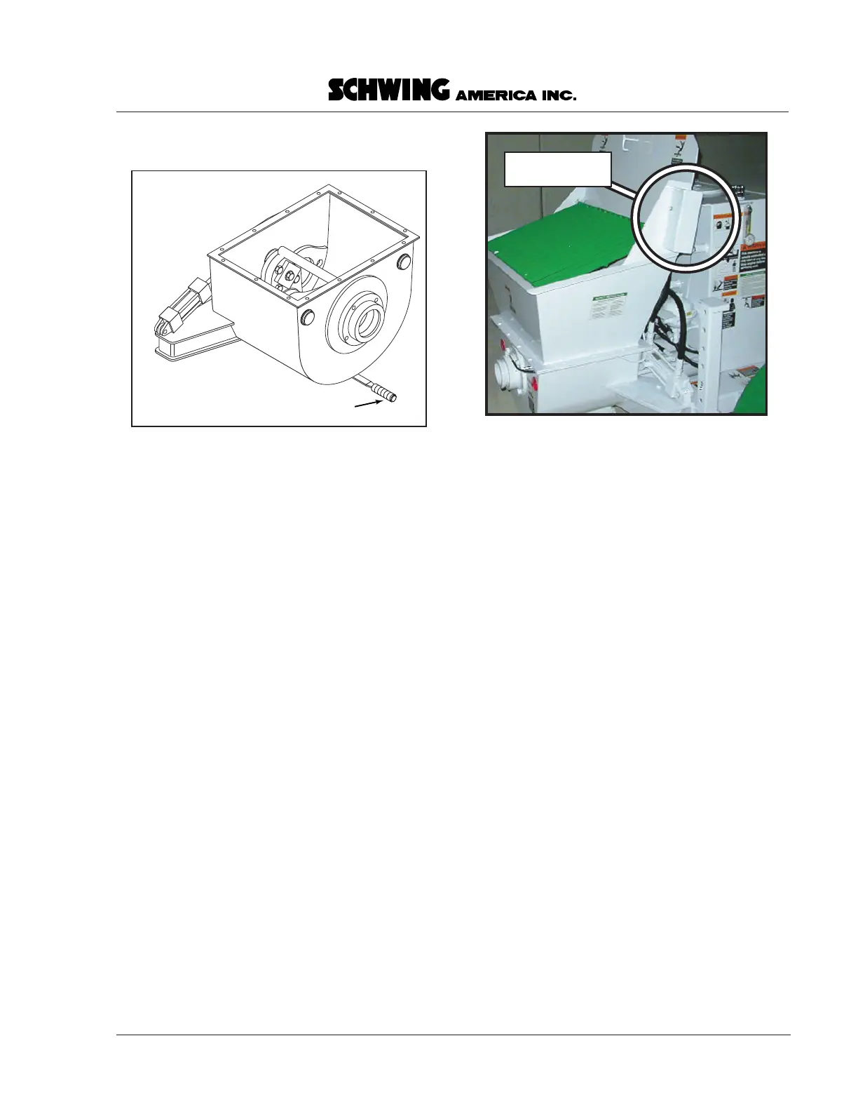
• Stop the unit. Open the cleanout cover on the
bottom of the concrete valve (Figure 23).
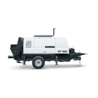
• Leave the hopper grate in place. Spray water
through the grate into the hopper to clean concrete
out of the corners and the concrete valve. If you
need to rotate the hopper grate to the open position
to chip away hardened concrete or for any other
reason, the pump must be stopped. To assure that
this is done, the electrical supply to the concrete
pump circuit is connected through an interlock
switch on the hopper grate. The pump will not
operate unless the hopper grate is shut, and the
pump will stop if you rotate the grate open while it
is running. Do NOT disable or bypass the hopper
grate interlock switch. It was installed for your
protection (Figure 24).
• Stop the pump. Spray water through the outlet pipe
into the concrete valve opening. One cylinder will
be exposed through the valve. Use the supplied
cleanout rake to dig out excess material. When you
have removed as much material as you can, switch
the concrete valve as instructed below.
NOTE!
Never put your hands into the concrete
valve!
• Make certain that no one is near the concrete valve
or the waterbox. Start the pump, and let it stroke in
reverse until the concrete valve switches to the
other material cylinder. Stop the pump again.
• Spray water through the outlet pipe into the
concrete valve and the material cylinder. The
opposite cylinder is now exposed through the
concrete valve. Again, NEVER reach into the
concrete valve with your hands. Use the supplied
cleanout rake to remove any material that won’t
come out with the water spray. Continue stopping
the unit, switching the concrete valve, and cleaning
until the water flows out clean and clear.
• Spray into the top of the hopper again, as some
material will have been washed into the hopper
area by cleaning the inside of the concrete valve.
When it is clean, close the cleanout door on the
bottom of the concrete valve housing.
• ALWAYS DRAIN THE WATERBOX AT THE
END OF EACH POUR. The reason for this to
prevent the oil from being contaminated by
water. Here’s how it happens:
As the oil cools after a pour, it creates a vacuum in
the differential cylinders. This vacuum causes the
water in the box to be pulled past the packing seals
of the cylinder and into the oil. The result is milky
oil.
• With the engine stopped, remove the waterbox
cover. Find the drain plug on the bottom of the
waterbox (Figure 25). Remove the plug by
unscrewing the T-handle until the plug becomes
loose. When the plug is out, the water will drain
out of the hole. Spray water into the waterbox, the
material cylinders, and around the tension rings
where the hydraulic cylinder rods come out of the
waterbox wall. Do not allow cement particles or
fine sand to build up. If you notice a layer of sand
or cement particles at the bottom, the rubber rams
need to be replaced. (For ram replacement
Cleanout door handle
Svlv.eps
Figure 23
Cleanout door
Hopper grate
interlock switch
intrlckswtch.eps
intrlckswtch.eps
Figure 24
The hopper grate interlock switch