Appendix
Operation Manual -
SP 30568
revDate
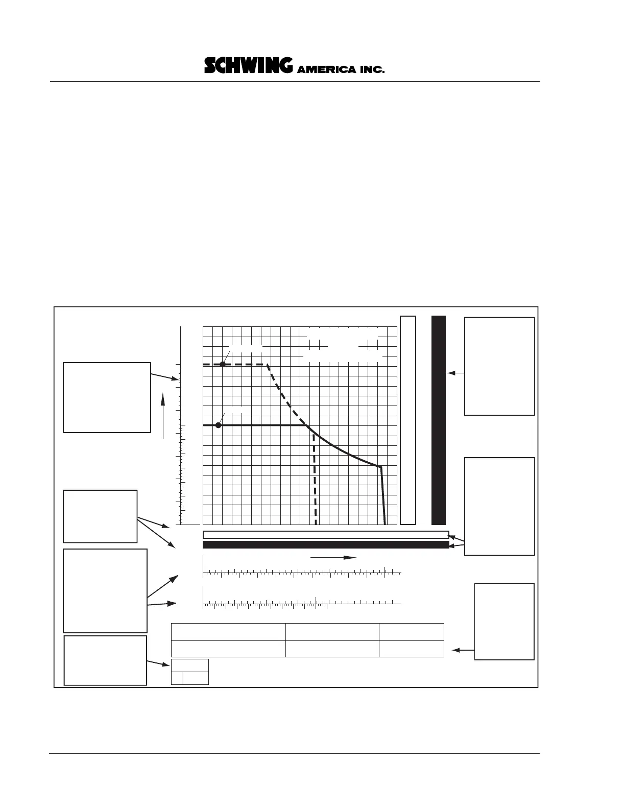
Output Charts
The hydraulic pumps that drive your concrete pump are
horsepower controlled. That means that when pressure
rises past a certain point (known as the breakpoint), the
pumps change their displacement per revolution,
resulting in less flow and fewer strokes per minute. The
reason for this is so the pumps will not stall your
engine by drawing too much horsepower. Output charts
show the horsepower curve (in kilowatts, or Kw) of the
concrete pump hydraulic circuit. From them, you can
determine the:
• maximum concrete pressure of the pumpkit
model,
• maximum output (in cubic yards per hour) of
the pumpkit model,
• maximum strokes per minute of your pumpkit
model,
• maximum output (in liters per minute, L/min)
of your hydraulic pumps,
• output that can be expected at various pumping
pressures,
• condition of your hydraulic pumps when used
in conjunction with a flowmeter, and
• breakpoint of your hydraulic system.
An explanation of an output chart is shown on the
following pages, followed by some examples of chart
usage. The output chart of the pumpkit shipped with
this manual is shown later.
Using the chart
Rev. 081997
Init.
SAIE 5240-
032
BPL 1200 HDR-23 - SP
230mm x 2000 mm
CONCRETE OUTPUT
NUMBER OF STROKES
(stroke / min.)
OIL VOLUME
(liter / min.)
NUMBER OF STROKES
(stroke / min.)
OIL VOLUME
(liter / min.)
117
ROD SIDE
Hydraulic relief valve is set at
350 bar max. pressure (5075 PSI).
Pump Speed
1900 RPM
Performance characteristics of
the axial piston hydraulic pump
130 mm / 80 mm x 2000 mm 2 x Voac V30D 140
2 x 92 KW
Differential Hydraulic Cylinder
Bore dia. / Rod dia. x Stroke length
Hydraulic Pumps
Type / KW
Material Cylinders
Bore dia. x Stroke length
PISTON SIDE
PISTON
SIDE
ROD
SIDE
510152025
51015202530
28.5
17.8
350
100 200 300 40050 150 250 500450
PISTON SIDE
(bar)
ROD SIDE
(bar)
1621
1007
OIL PRESSURE
350
50
100
150
200
250
300
50
100
150
200
250
300
350
30
187
Slewing cylinder 80 / 45 x 185
100 200 300 400 500
PSI
100
200
300
400
500
600
700
800
900
1000
1100
1200
1300
1400
1500
1600
1700
1800
1900
2000
Bar
7
14
21
28
34
41
48
55
62
69
76
83
90
97
103
110
117
124
131
138
cu yards/ hr
7 15 23 30 38 46 53 61 69 76 84 92 99 107 115 122 130 138 145 153
cu meters/ hr
20 40 60 80 100 120 140 160 180 200
concrete pressure
0
THE PERFORMANCE CURVE INDICATES THAT THERE IS NO ALLOWANCE FOR
FILLING EFFICIENCY OF THE CONCRETE CYLINDER.
Breakpoint
=199 bar
Min Q
@ 350 bar
=284 l/m
Concrete
pressure is
shown here.
Max. pressure
is shown for
both piston
and rod side
configurations.
Concrete
output is
shown here,
with max.
shown for both
piston and rod
side
configurations.
Information
about the
pumpkit and
hydraulic
pumps is
shown here.
Hydraulic liters per
minute, and the
corresponding
strokes per minute,
for both piston and
rod side.
The breakpoint
specification are
listed here.
and minimum Q
The Schwing ISO
and revision date
are listed here.
document number
000026.eps
Hydraulic oil
pressure shown
here, ranging from
zero to the relief
valve setting.