Maintenance
Startup 250:Users:Danny:Desktop:Operation manuals:line pumps:maverick
(P305):pHseriesMAINTENANCE.fm
59
Operation Manual - SP 305
4. Activate the pump in reverse mode, bringing the
piston cup down to the end of the material cylinder.
The pump will pressure out before the S-tube
shifts, because the shutoff valve is closed; however,
you should be able to stop the pump and have
access to the piston cup before the pump pressures
out.
5. Push the emergency stop button on the operator’s
panel and stop the engine. Put the key in your
pocket, and verify that the pressure gauge is
showing zero.
6. Remove the hopper on the SP 305 by removing all
of the hopper mount bolts.
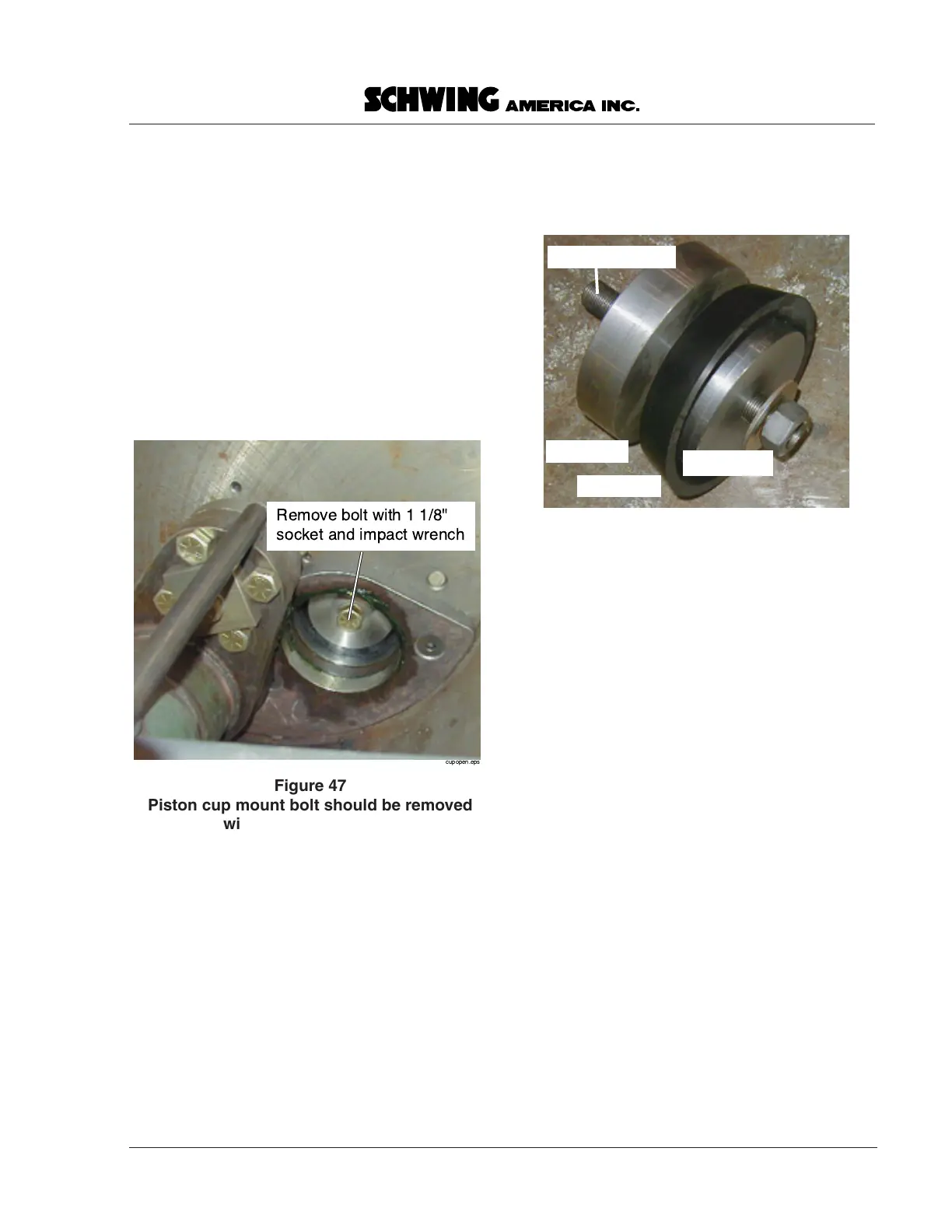
7. Place a 1 1/8” socket on an impact wrench, and
remove the center mount bolt (Figure 47).
8. Remove the piston cup assembly from the material
cylinder.
NOTE!
If the cup won’t slide out easily: start the
engine, release the e-stop, and activate the
pump in forward mode just long enough to
pull the rod away from the piston cup. Stop
the pump before the cylinder reaches the
end of the stroke, push the e-stop button,
stop the engine, and put the key back in
your pocket.
After verifying zero pressure on the gauge,
use a screwdriver or small pry tool in the
center bolt hole to remove the piston cup.
9. Separate the components (Figure 48), and clean all
residue from the face plate and O-ring back plate,
as well as the O-ring groove.
10. Install the new O-ring on the back plate, and apply
a coat of grease to the entire O-ring.
To install the new ram
1. Start the engine and run the piston rod back down
to the end of the stroke, stop the engine, push the e-
stop button, and put the key in your pocket.
NOTE!
An alignment/installation tool is supplied
for installing the new ram. If the alignment
tool is lost, it may be helpful to cut the head
from a 3/4” bolt that is 3 to 4 inches long,
screw the alignment bolt into the end of the
rod, and slide the components over the bolt
to reinstall.
2. The back side of the O-ring back plate is keyed for
the purpose of rod alignment. This keyway, or pilot
hole, should also be greased lightly before being
placed on the alignment pin.
3. Push the back plate into the material cylinder, and
align the pilot with the end of the rod.
4. Grease the new piston cup, and slide it over the
alignment pin with the flat side to the back plate, as
shown in Figure 48.
Figure 47
Piston cup mount bolt should be removed
with an impact wrench
cupparts.eps
Back Plate
Piston cup
Face Plate
Installation tool
Figure 48
Piston cup components