4
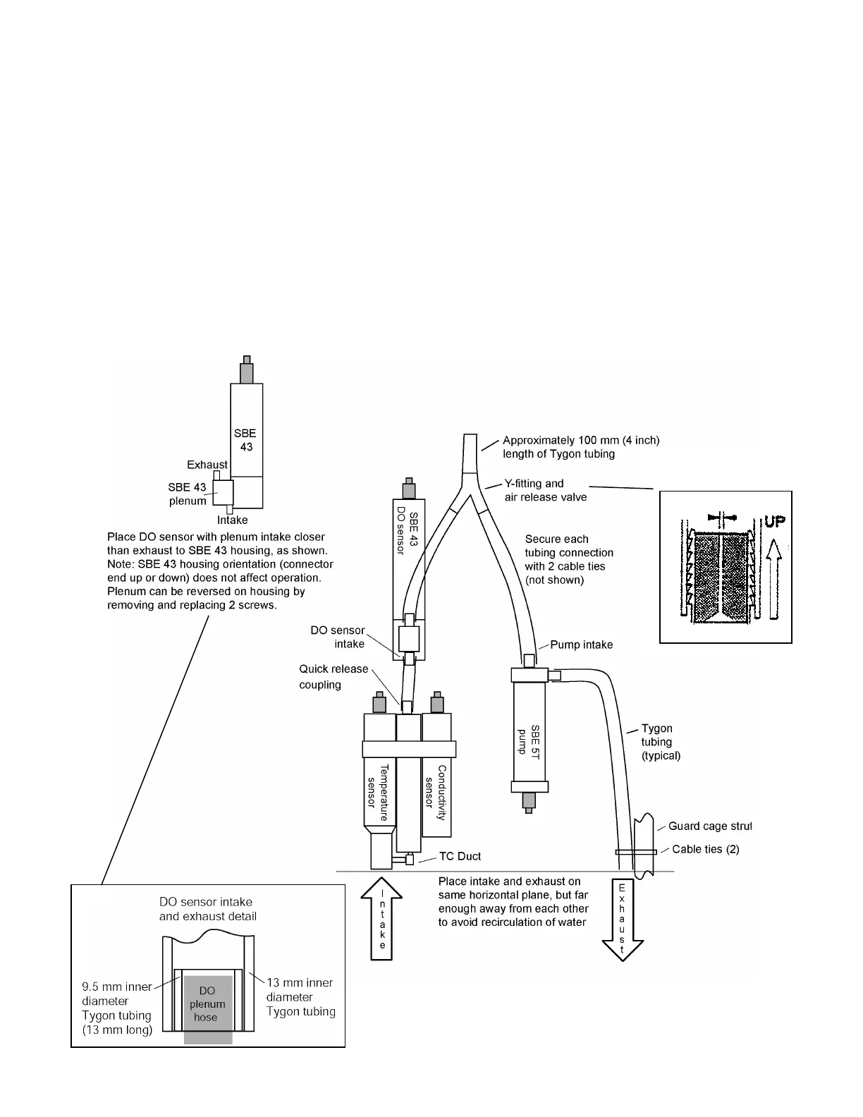
Vertical Configuration Schematic and Details
When installing plumbing for the vertical configuration:
• (For SBE 9plus only) Place the opening of the intake and exhaust on the same horizontal plane. Attach exhaust
tubing from the pump to the cage, as shown in the schematic below. Failure to place the exhaust tubing properly
can lead to acceleration of water in the plumbing, with resulting errors in conductivity data.
Note: Exhaust tubing is usually omitted by Sea-Bird for an SBE 19, 19plus, 19plus V2, or 25.
• Place the exhaust away from the intake, so that exhaust water is not pulled into the intake. If the exhaust is too
close to the intake, it will cause errors in temperature data, because the pump transfers heat to the exhaust water.
• Place a 13 mm (0.5 inch) long piece of 9.5 mm ID Tygon tubing at the DO sensor intake and exhaust. Slide the
larger diameter Tygon tubing (13 mm ID) over the smaller diameter tubing to provide tight seals.
• SBE 5T titanium pump, which is standard for the 9plus, is shown in the diagram. SBE 5P plastic pump has the
same operational characteristics, and may be ordered with the SBE 19, 19plus, 19plus V2, or 25 CTD for
deployments to 600 m.
• If the system does not include a DO sensor, connect the tubing from the conductivity cell directly to the
Y-fitting.
Air release valve detail
Note: Periodically clean air
release valve to ensure
proper functioning.
0.5 mm (0.02 in.)
232