38
CONTROLS, COMPONENTS AND INSTRUMENTS
FUNCTIONS
1) Safety Lanyard
(engine cut-out switch)
The safety lanyard cap should be se-
curely snapped onto its switch to be
fully operational.
Pulling the safety lanyard cap from the
switch stops the engine operation. At-
tach the safety lanyard to the opera-
tor’s Personal Flotation Device (PFD)
and snap the cap to the switch to be
able to start the engine.
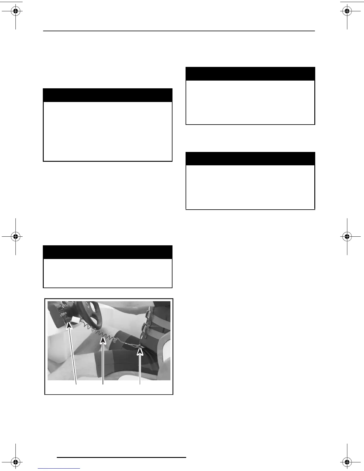
TYPICAL
1. Safety lanyard
2. Secure to PFD
3. Snap to safety lanyard switch
CAUTION: Do not lubricate the safe-
ty lanyard post.
2) Steering Wheel
The steering wheel controls the direc-
tion of the boat. Turning the steering
wheel clockwise steers the boat to the
right and inversely.
Low-Speed Steering Control
Systems
Whenever the engine RPM is at idle
and the steering wheel is approaching
the end of its rotation, the engine speed
will be slightly accelerated to increase
the jet pump thrust and thus improving
the steering control for low speed oper-
ation and when approaching/leaving a
dock. Refer to OPERATING INSTRUC-
TIONS for more details.
3) Throttle/Shifter Lever
Shifter Lever
A 3-position lever:
– forward
– neutral
– reverse.
WARNING
Always use the safety lanyard
when operating your boat to help
prevent a runaway boat and re-
duce the risk of personal injury or
death. Disconnect the lanyard
when stopped to help prevent ac-
cidental starting.
WARNING
Should the safety lanyard become
loose or fails to remain on its
switch, replace it immediately.
F09L06Y
12
3
WARNING
Directional control is reduced
when throttle is decreased and
lost when engine is off. Always
disconnect safety lanyard when
boat is not in operation.
WARNING
While the engine can be stopped
using the ignition switch, good
driving habits recommend that the
safety lanyard also be disconnect-
ed when stopped.
lmo2005-006a_1.book Page 38 Wednesday, July 7, 2004 1:06 PM