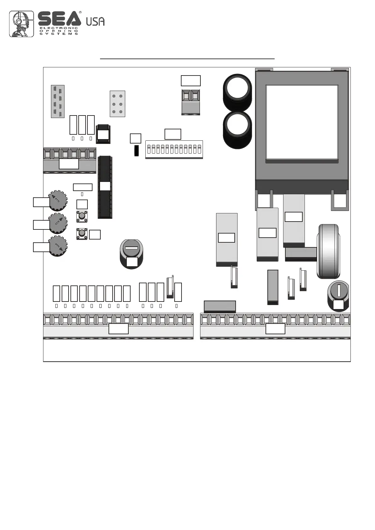
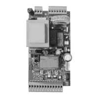
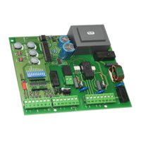
CN3CN2
RL1
RL2
RL3
F1
F2
P1
P2
Rv1
Rv2
Rv3
CN1
U1
U2
DIP
J1
LED5
LED6
LED7
LED8
LED9
LED10
LED11
LED1
LED2
LED3
LED4
LED12
LED13
LED14
LED15
LED16
CMR
LEDPLEDP
CNP
CN4
GATE 2
5
PARTS SPECIFICATION
LED1 = Auxiliary input
LED2 = Partial Start
LED3 = Start
LED4 = Limit switch in closing Motor 2
LED5 = Limit switch in opening Motor 2
LED6 = Limit switch in closing Motor 1
LED7 = Limit switch in opening Motor 1
LED8 = Photocell 2
LED9 = Photocell 1
LED10 = 24V Auxiliary output
LED11 = Tx Photocell output
LED12 = Troubleshooting LED
LED13 = Electric Lock
LED14 = Encoder (reversing sensor) 2
LED15 = Encoder (reversing sensor) 1
LED16 = Stop
LEDP = Programming
CN1 = 24V input / output connector
CN2 = 24V input / output connector (green)
CN3 = Motors and Power supply connector (orange)
CN4 = 24Vac Photosync connector
Rv1 = Motor torque adjustment
Rv2 = Brake length adjustment (slow down length)
Rv3 = Pause time adjustment
P1 = Operating time memory button
P2 = Programming transmitters button
DIP = Dip-switch Function Setting
F1 = Output and motor fuse (6.3AT)
F2 = Accessories fuse (2A)
J1 = Slow-down adjustment
RL1 = Motor Power Supply Relay
RL2 = Motor Operating Direction Relay
RL3 = Garden Light Relay
U1 = Micro-controller
U2 = EEPROM memory
CNP = PALM connector
CMR = Receiver module connector
International registered trademark n. 2.777.971
REV 05 - 10/2010
GREEN ORANGE