M4200 - User manual
Revision: 07.03.2017 Page 14
Programming by switches
There are two ways of programming the alarm monitor; by dip switches on the rear of the unit or by any
standard ANSI compatible terminal application e.g. Microsoft
®
HyperTerminal (which is supplied with the
Windows
®
operating system) or any other ANSI terminal.
When using a standard ANSI compatible terminal application, the configuration is done through a PC, via the
special RS232 cable, which is delivered with the M4200 unit.
This section only contains information about programming by dip switches.
Switches
All switches needed for programming are located on the rear of the alarm monitor. There is 1 rotary switch
with 10 channels for mode selection and 2 rows of dip switches with each 8 dip switches for choosing
different programming facilities.
Below is a description of the functions, both on the rotary switch and the dip switches.
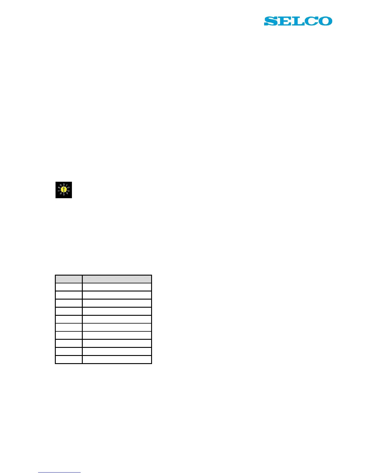
Rotary switch - operational principle
Below is an explanation of the different modes on the rotary switch. Figure 10 illustrates the different modes
schematically.
Position “0” is operational mode. This mode is default selected and means that the alarm monitor is running
in alarm mode.
Position 1 – 8 is programming mode for each of the input channels. Programming functions into channel 1,
set the rotary switch in position 1 etc.
Position 9 is programming mode for general functions, such as block, delay and reset functions.