M4200 - User manual
Revision: 07.03.2017 Page 6
Multiple units
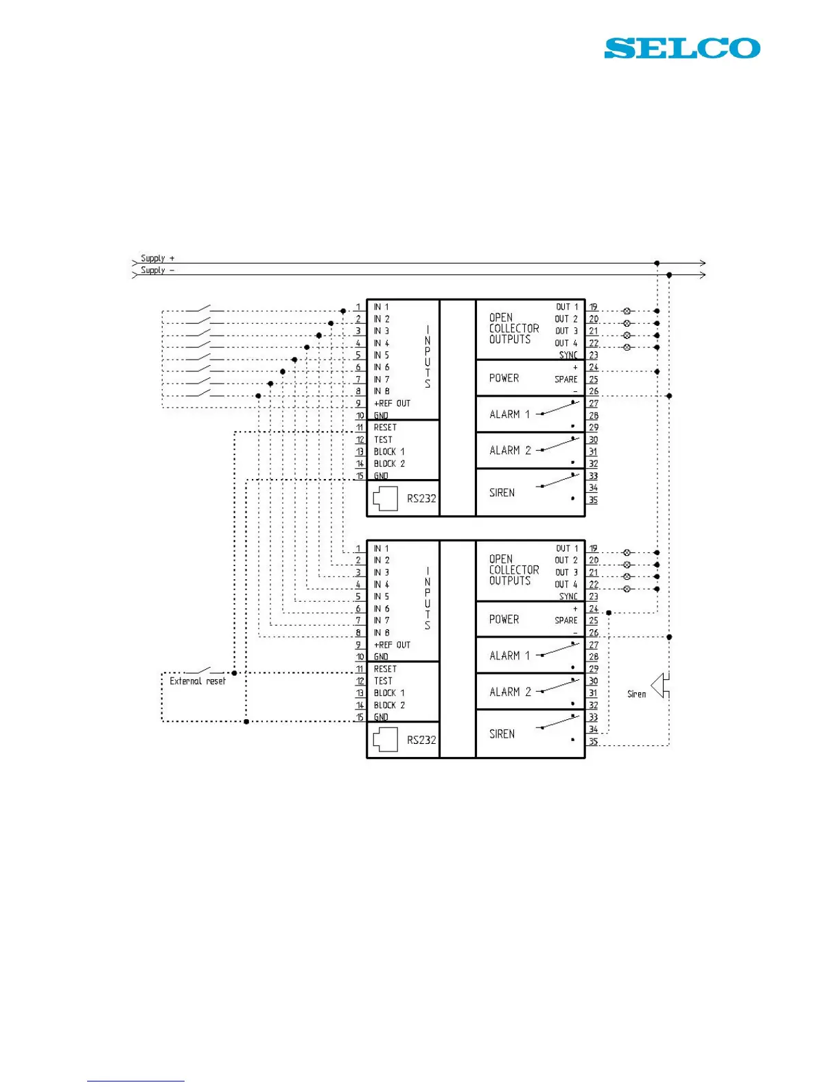
Figure 3 shows the default connection of the input and output terminals on two M4200 units. Input terminals
1 - 8 are connected to +REF OUT (positive supply) on one of the units via potential free contacts.
Test terminals are connected to GND on both units via potential free contacts (test and block terminals can
be connected by the same method).
Lamps are connected to the outputs; the lamps are supplied from same source as the units. Terminal 26 is
connected to ÷ (negative supply).
Figure 3. Wiring example, multiple units with external reset (default connection).
Synchronisation
If multiple units are positioned side by side it can be desirable that all LEDs, on all the units are flashing with
the same speed rate.
If all Sync terminals (23) on all the multiple units are connected with each other, all LEDs will operate with the
same speed rate.
No further configuration is needed. The Sync functionality has no other importance than providing visual
continuity.