M4200 - User manual
Revision: 07.03.2017 Page 3
Introductory notes
This manual describes installation and operating instructions together with dip switch configuration of the
Alarm Monitor M4200.
This manual also includes information about how to configure the product, using the included RS232 cable
and a Windows
®
PC running Microsoft
®
HyperTerminal.
Layout
Below is a description of the facilities on the front and the rear of the unit.
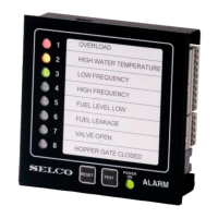
Facilities on the front
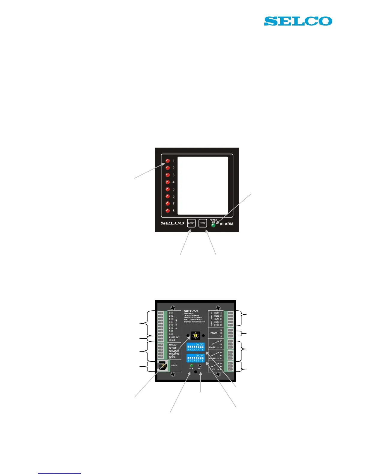
Facilities on the rear
Output terminals. 4 open collector outputs for
remote control of external lamps or relays.
Sync. Used for synchronization of flashing LEDs
on multiple M4200 units.
8 LEDs, one for each input
terminal. By programming it
is possible to change the
colour individually for each
LED, into red, green or
yellow.
When reset button is pushed,
all relay outputs go off and
LED status change from
flashing to steady mode
When test button is pushed, all LEDs
show steady light. Hold down the button
and test status will change from red into
green and into yellow.
Keep down the button and dimming of all
LEDs can be done in 8 consecutive levels.
Green LED. Active
when power is on.
+REF and GND. Reference to inputs. +REF is
the same as positive power reference. GND is
galvanically separated from the negative power
reference.
Reset, test and block functionality for remote
activation. GND is common reference.
RS232 interface. Used for connection with PC.
Power. Terminal 24 is positive reference.
Terminal 26 is negative reference. Terminal 25 is
not in use.
Output relays. Alarm 1 is default activated when
inputs are active. It is possible to set up activation
mode for both alarm 1 and 2.
Siren relay. Default activated when inputs are
active. It is possible to set up activation mode for
the siren relay.
Input terminals. Used for connection of potential
free contacts. Both NO and NC contacts are
supported.
10 channel rotary switch. Used for
switch configuration of the unit:
0: Operational mode
1 - 8: Set input 1 - 8
9: Set general functions
Acknowledge LED.
Indicates that programming
by set button is accepted.
8 dip switches. Used for configuration of
the unit. Named in documentation as 1-1
to 1-8.
Set button. Used for
accept of rotary and dip
switch settings.
8 dip switches. Used for configuration of
the unit. Named in documentation as 2-1
to 2-8.