M4200 - User manual
Revision: 07.03.2017 Page 5
Installation instructions
This section contains information about how to install the alarm monitor.
Single unit
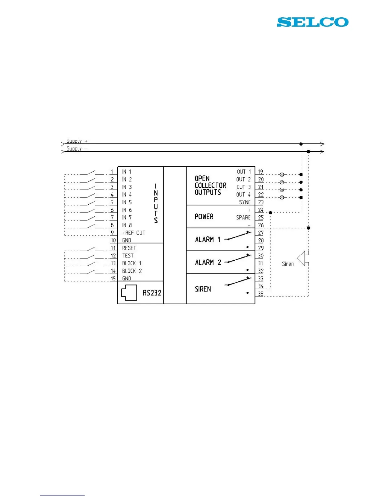
Figure 2 shows the default connection of the input and output terminals on the alarm monitor. Input terminals
1 - 8 are connected to +REF OUT (positive supply) via potential free contacts.
Reset, test and block terminals are connected to GND via potential free contacts.
Lamps are connected to the outputs; the lamps are supplied from same source as the unit. Terminal 26 is
connected to ÷ (negative supply).
Figure 2. Wiring example, single unit (default connection).