13
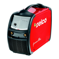
2.4 Installation
- Put the WU on the GT and block it with the 4 screws.
- Position the power source above the cooling unit and secure
it by means of the screws.
Perform the following operations before starting
the unit:
- Remove the refill neck cap.
- Remove the sealing cap from the refill neck, levering by
means of a tool on the edge of the cap.
- Fill the tank with cooling liquid if necessary.
- Keep apart the sealing cap for future transport of the unit.
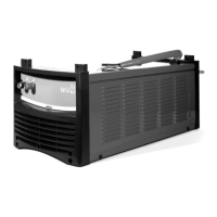
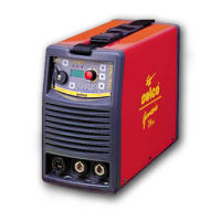
Connection for TIG welding
- Connect the red hose of the torch to the appropriate inlet
quick connector (1) (red colour - symbol
).
- Connect the blue hose of the torch to the appropriate outlet
quick connector (2) (blue colour - symbol
).
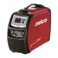
Connection for MIG/MAG welding
- Connect the blue hose of the cable bundle to the appropriate
outlet quick connector (4) (blue colour - symbol
).
- Connect the red hose of the cable bundle to the appropriate
inlet quick connector (5) (red colour - symbol
).
In order not to damage the cooling unit, always
fit the by-pass pipe (3) when the torch is not con-
nected to the cooling liquid inlet/outlet termi-
nals.
Filling or topping up of the tank must be per-
formed with cooling liquid, code 18.91.001.
3 SYSTEM PRESENTATION
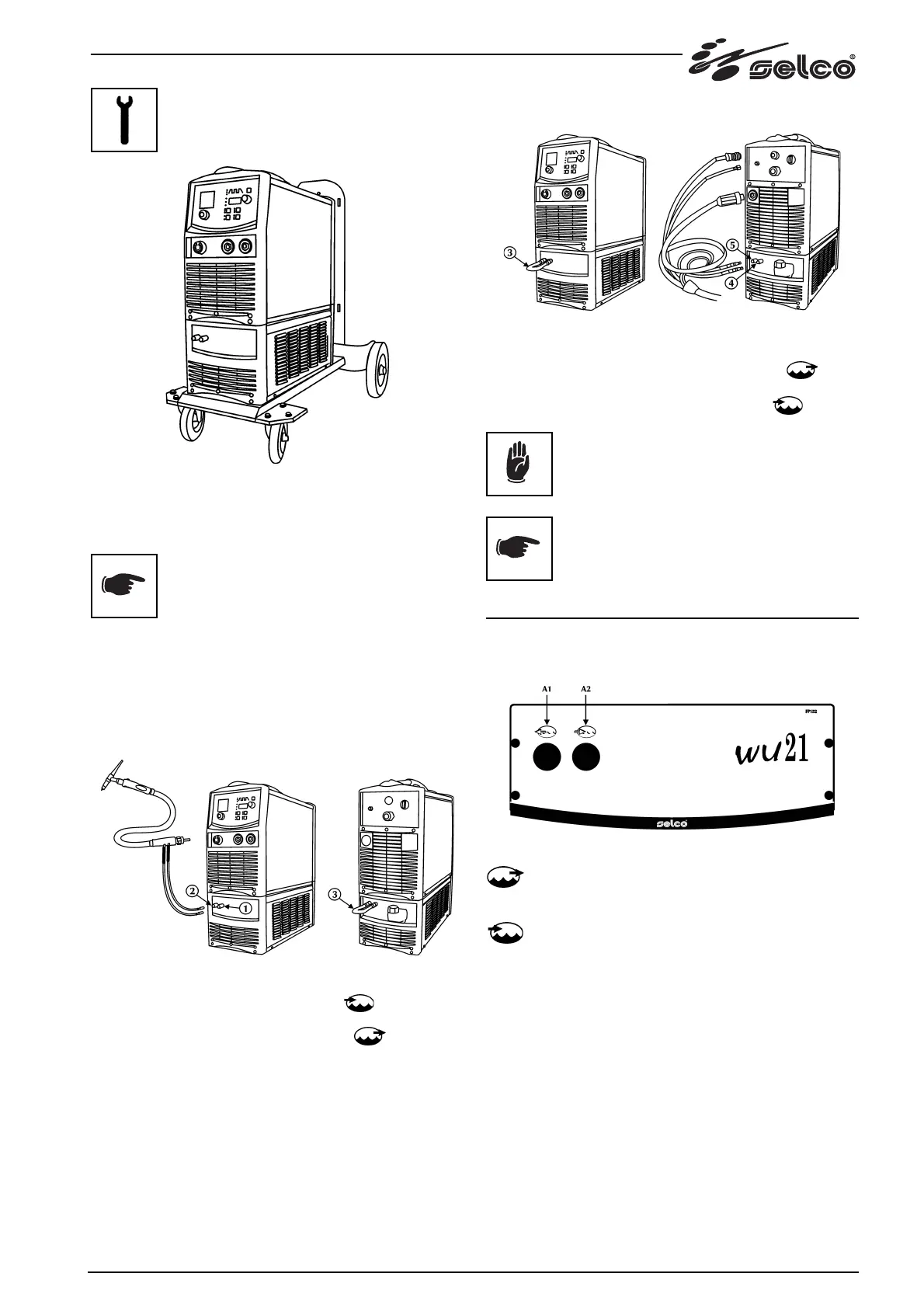
3.1 Front panel
A1: cooling liquid outlet connector.
To supply low temperature liquid into the torch cooling
circuit.
A2: cooling liquid inlet connector.
To return the liquid that has been heated by the torch
into the cooling circuit inside the WU.